

Prestressing shot-blasting formation technique for double-curved wallboard
A shot peening and prestressing technology, applied in the field of manufacturing, can solve the problems of limited forming ability and difficult final forming of large wing panels
- Summary
- Abstract
- Description
- Claims
- Application Information
AI Technical Summary
Problems solved by technology
Method used
Image

Examples
Embodiment Construction
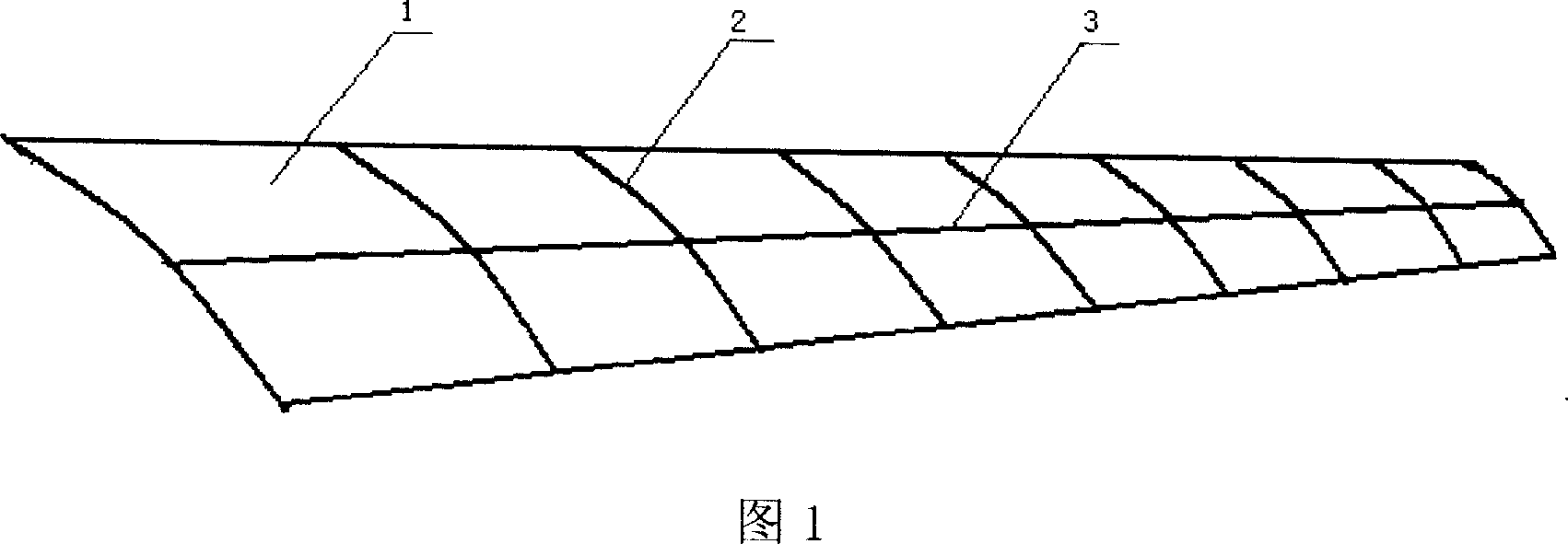
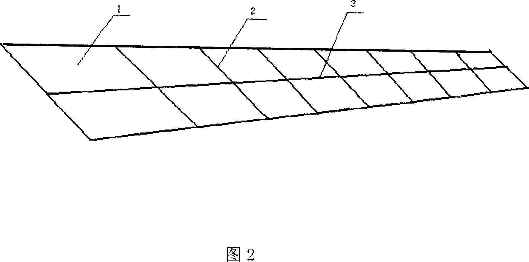
[0021] See the accompanying drawings: The theoretical shape shown in Figure 1 is a double-curvature structure, and its chord curvature is represented by several transverse rib lines 2 on the wall plate 1, and its span curvature line 3 is defined by the wall plate The central longitudinal line of is used as the representative curvature line. The technical problem solved by the present invention is to pre-bend and clamp the unfolded panel as shown in Figure 2 with a prestressing fixture, so that the pre-bending state of each rib line and spanwise curvature line on the panel conforms to Figure 1 The theoretical shape is shown, and then the wall panel parts are shaped by shot peening.
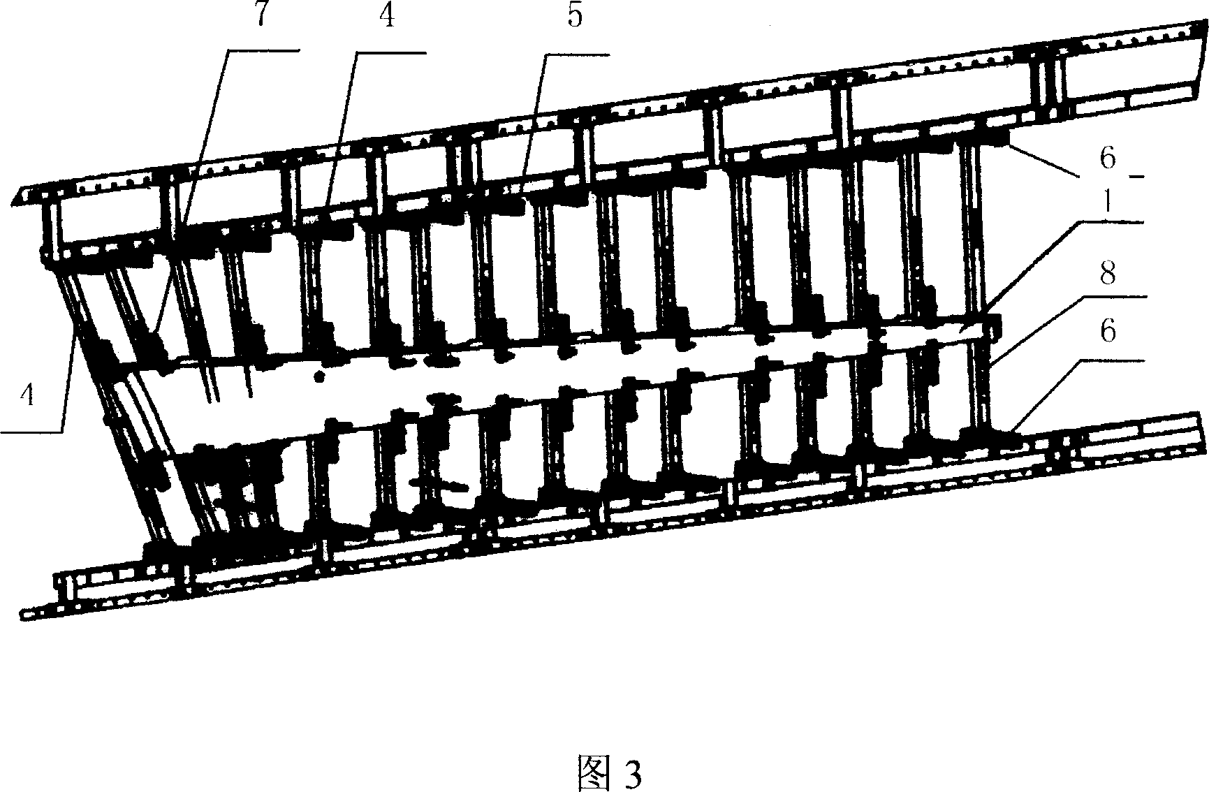
[0022] The prestressing fixture used in the present invention is shown in Figure 3, is formed a rigid framework by several columns 4 and beam 5 and beam guide rail 6, and the quantity of column 4 and the fixed position on beam guide rail 6 can be flexibly adjusted. The forming column is provided w...
PUM
 Abstract
Description
Claims
Application Information