Automatic soil eliminating construction apparatus for deep foundation groove

A technology for construction devices and deep foundation pits, which is applied in infrastructure engineering, earth movers/excavators, excavation, etc., which can solve problems such as difficulties in safe construction management, low construction efficiency, and partial under-excavation, and achieve benefits to the site Construction management, high construction efficiency, and low environmental impact

Active Publication Date: 2007-10-03
SHANGHAI URBAN CONSTRUCTION MUNICIPAL ENGINEERING (GROUP) CO LTD
View PDF0 Cites 12 Cited by
  • Summary
  • Abstract
  • Description
  • Claims
  • Application Information

AI Technical Summary

Problems solved by technology

This foundation pit excavation method generally adopts the construction sequence of sloping excavation, which not only has low construction efficiency, but also takes up a considerable amount of work time for foundation pit construction, and because there are different excavation equipment and operators in charge of different excavation In the soil area, in the process of grading excavation, it is easy to cause uneven excavation, local under-excavation and local over-excavation,

Method used


Image

  • Automatic soil eliminating construction apparatus for deep foundation groove
  • Automatic soil eliminating construction apparatus for deep foundation groove
  • Automatic soil eliminating construction apparatus for deep foundation groove

Examples


Embodiment Construction

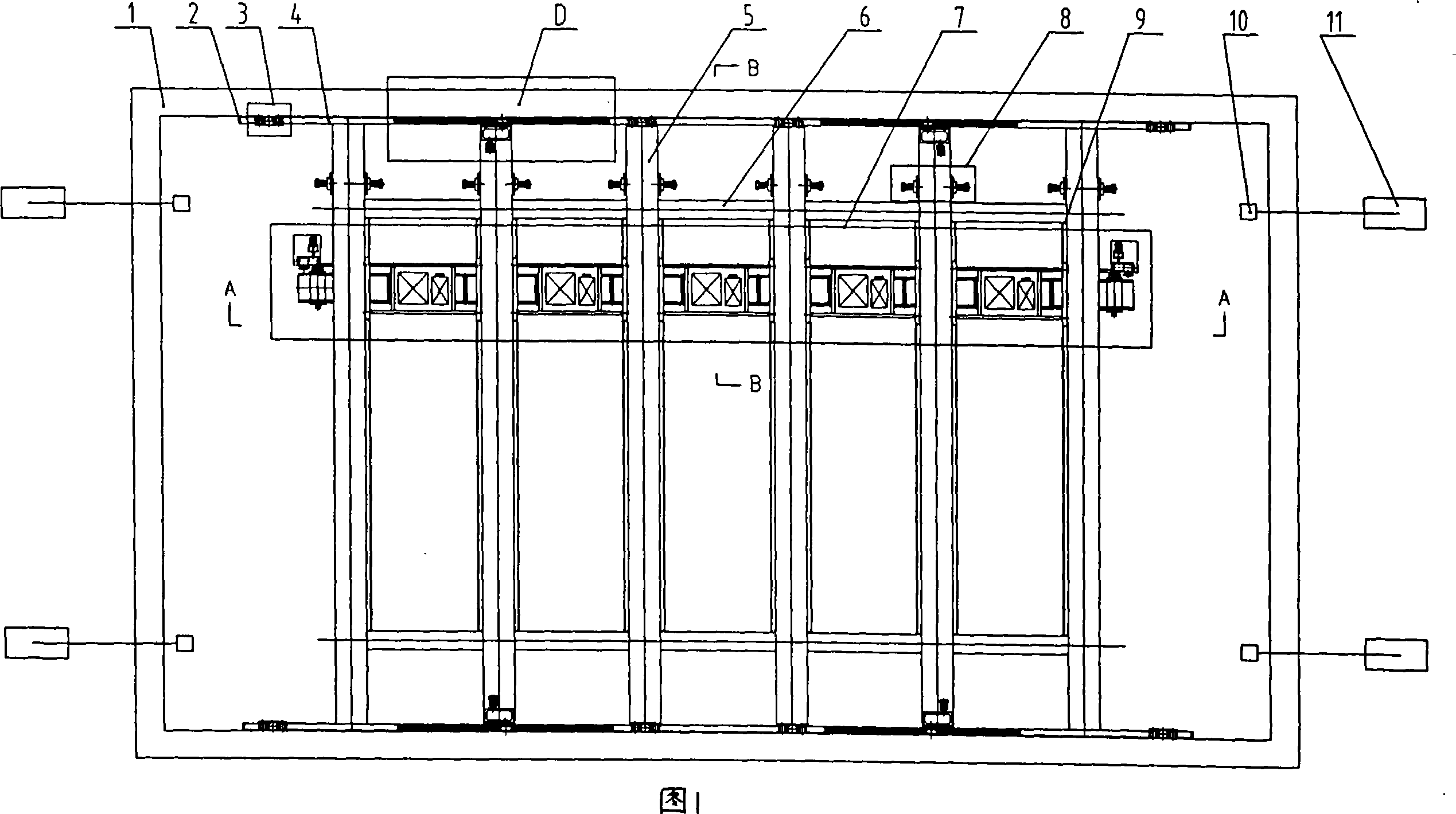
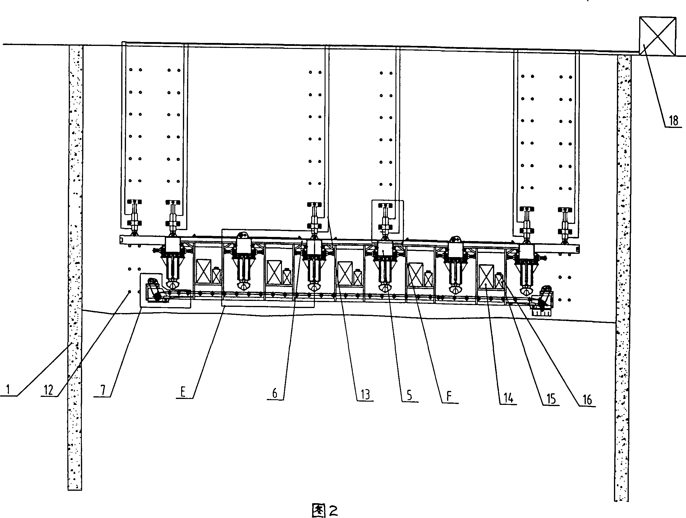
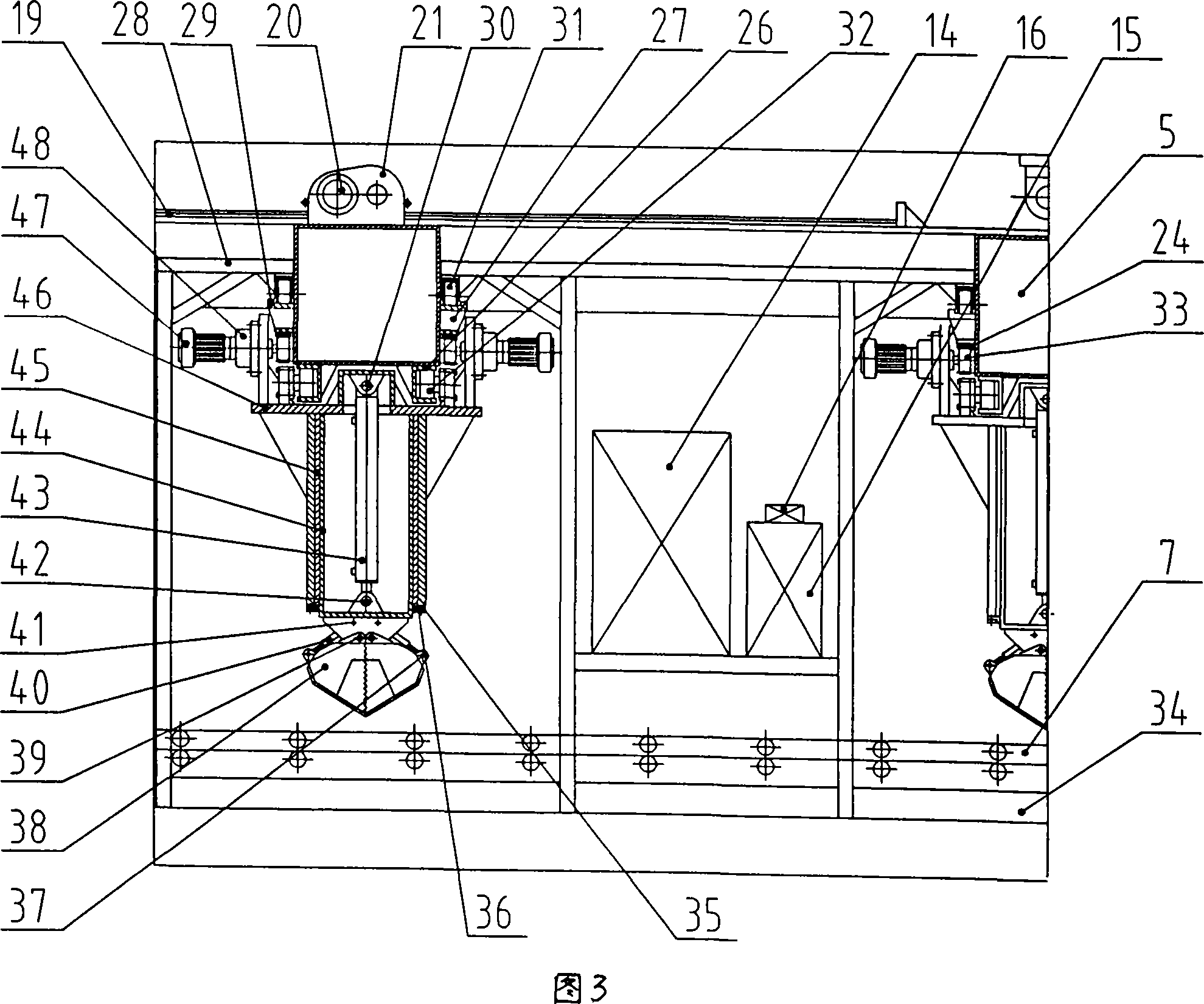
[0020] The features of the present invention and other related features will be further described in detail below in conjunction with the accompanying drawings through embodiments, so as to facilitate the understanding of those skilled in the art:

[0021] As shown in Figure 1-9, the labels 1-57 respectively represent: underground diaphragm wall 1, elastic limit block 2, self-climbing and descending device 3, track beam 4, walking beam 5, connecting beam 6, belt conveyor 7, hydraulic Grab excavation device 8, elastic limit block 9, mechanical grab 10, crawler crane 11, embedded pin seat 12, hydraulic hose 13, hydraulic power equipment 14, electrical control box 15, wireless remote control receiving device 16 , hinge seat 17, hydraulic power unit 18, rack 19, motor 20, reducer 21, gear 22, elastic limit block 23, rack 24, traveling wheel 25, track 26, rib plate 27, equipment frame 28, Track 29, pin 30, road wheel 31, road wheel 32, gear 33, connecting beam 34, dustproof rubber ...


PUM


Abstract

The present invention relates to excavating technology, and is especially automatic soil eliminating construction apparatus for deep foundation groove. The apparatus has several movable orbit beams in two vertical directions, one vehicle frame on the orbit beams, one belt conveyer capable of being shifted in the excavated area, and one power control device to control the motion of the vehicle frame on the orbit beams, so as to drive the belt conveyer discharging dug soil. The present invention has the advantages of high construction efficiency, high safety, less influence on peripheral environment, etc.

Description


Claims


Application Information

Patent Timeline
Owner SHANGHAI URBAN CONSTRUCTION MUNICIPAL ENGINEERING (GROUP) CO LTD
Why Eureka
Try Eureka