
Glass hood cooking fume exhauster

A range hood and glass cover technology, which is applied in the field of kitchen range hoods, can solve problems such as difficult disassembly and cleaning, poor ventilation, and shortened service life of impellers, so as to prevent oil fume from polluting the environment, improve the efficiency of range hood, and reduce the entry of oil fume mouth effect

Inactive Publication Date: 2012-06-27
朱钦浩
View PDF1 Cites 0 Cited by
  • Summary
  • Abstract
  • Description
  • Claims
  • Application Information

AI Technical Summary

Problems solved by technology

The glass cover range hood has smooth lines and beautiful appearance. It mainly serves as a decoration for the cabinet. The function of removing oil fume is quite poor. The service life of the impeller is difficult to remove and wash
The drooping filter screen and the oil cup are stuck with dirty oil, which seriously affects the appearance of the range hood and the cleanliness of the cabinet
When the oil fume rises, a lot of oil fume overflows the outside of the range hood, leaving the suction range of the range hood, causing pollution to the kitchen environment
When the lighting is enabled, the left stove should use the left light, and the right stove should use the right light. If the left and right stoves are used at the same time, it is inconvenient to use two lights.
Part of the oily fume generated in the kitchen is filtered by the filter and concentrated into the oil cup, and part of it is discharged outdoors, causing outdoor environmental pollution
The small area of ​​the filter screen is in direct contact with the oil fume, and it is easy to be blocked by the oil fume. It must be washed frequently, otherwise the poor ventilation will make the oil fume absorption function worse and cause serious pollution to the kitchen environment.

Method used


Image

  • Glass hood cooking fume exhauster
  • Glass hood cooking fume exhauster
  • Glass hood cooking fume exhauster

Examples


Embodiment Construction

[0024] The present invention will be further described in detail below in conjunction with the accompanying drawings and embodiments.

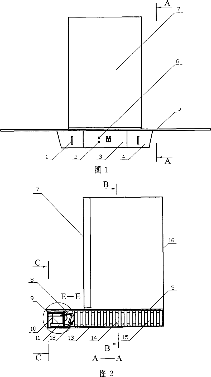
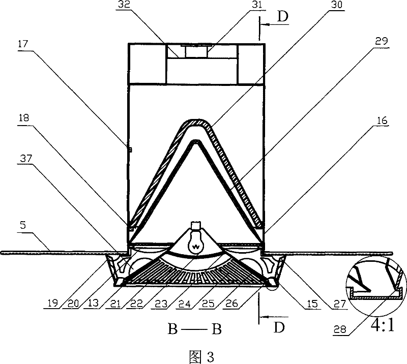
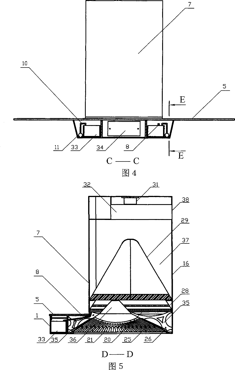
[0025]With reference to the accompanying drawings, the present invention is provided with a smoke collecting chamber 16, the lower end of the smoke collecting chamber 16 has an outward turning edge before and on the left and right sides, the glass cover 5 is hung on the turning edge of the lower end of the smoke collecting chamber 16 and fixed, 5. The lower smoke collection cavity 16 is turned over and fixed with more than six fixed plates 35 around the upper periphery. The side ventilation inner wall 21 is installed on the inner side between the fixed plates 35. The vertical slot air inlet 24 at the bottom of the side ventilation inner wall 21 can be disassembled in pieces. An illuminating lamp 22 and a lampshade 23 are disposed in the middle of the reflector 36 . The left and right outer sides of fixed plate 35 are fixed two side air intake ...


PUM


Abstract

The invention discloses a glass cover extactor hood including a smoke-collecting cavity, a side ventilation inner wall, a side intake air cover, a control box, a fan, a composite filter screen, a filter medium, an oil tray, a glass cover and an oil pump or the like. The glass cover is arranged at the lower end of the smoke-collecting cavity and is fixed. A motor is arranged at an upper part in the smoke-collecting cavity. The lower part of the motor is connected to the fan. The invention is characterized in that a fixed plate is fixed under the smoke-collecting cavity of the glass cover extactor hood, one side intake air cover is respectively fixed on the left side and the right side out of the fixed plate, the side ventilation inner wall is fixed at the middle, the lower end of the side intake air cover is connected to an oil tank, the periphery of the lower end of the side ventilation inner wall is arranged in the oil tank, and the control tank is arranged in front of the side intake air cover. The invention has the advantages of concise and beautiful appearance due to the inner-hidden filter screen and an oil cup, small volume and energy consumption, small noise and easy and convenient unpicking and washing, long service life, high oil and smoke absorption efficiency, and clean and hygienic exhausted air. Two side suction is strong to match the characteristics that stoves are arranged at two sides of kitchen range, so that the oil and smoke is not spilled.

Description

technical field [0001] The invention relates to a range hood for kitchen use, in particular to a range hood with a glass cover which has a strong range hood function and discharges clean and hygienic air. Background technique [0002] At present, the suction port of most range hoods is in the middle of the upper part of the range hood, and the lighting lamps are arranged on both sides of the range hood. When the range hood is working, the range hood is strong in the middle, and the suction on the left and right sides is weak, which does not match the structure of the stove on the left and right sides of the cooker. The glass cover range hood has smooth lines and beautiful appearance. It mainly serves as a decoration for the cabinet. The function of removing oil fume is quite poor. The service life of the impeller is difficult to disassemble and wash. The drooping filter screen and the oil cup are stuck with dirty oil, which seriously affects the appearance of the range hoo...

Claims


Application Information

Patent Timeline
Patent Type & Authority Patents(China)
IPC IPC(8): F24C15/20
Inventor 朱钦浩
Owner 朱钦浩
Learn More