
Pressure-measuring fiber grating process and device

A fiber grating and measurement method technology, which is applied in the measurement of the change force of the optical properties of the material when it is stressed, the use of diffractive elements to generate spectrum, spectrum generation and other directions, can solve the problem of poor long-term stability, large volume and slow response speed. and other problems, to achieve the effect of large range and high measurement accuracy

Inactive Publication Date: 2007-10-03
SHANDONG UNIV OF SCI & TECH
View PDF0 Cites 18 Cited by
  • Summary
  • Abstract
  • Description
  • Claims
  • Application Information

AI Technical Summary

Problems solved by technology

The mechanical and hydraulic mine pressure observation instruments are simple in structure, reliable in operation, and low in cost, but have disadvantages such as slow response speed, low precision, and large volume; the resistance strain sensor is based on the mechanical deformation of the metal wire under the action of external force. , and its resistance value changes due to the resistance strain effect. It is more sensitive and accurate than mechanical and hydraulic sensors, but this type of sensor has disadvantages such as sensitivity to temperature and poor long-term stability; the vibrating wire sensor is at 80 It was successfully developed and applied in the early 1990s. It uses the principle of steel strings with different fixed frequencies under different tensions to realize force detection. It is currently the most commonly used instrument in mine pressure detection, but this type of sensor still exists. Defects such as low precision and slow response speed

Method used


Image

  • Pressure-measuring fiber grating process and device

Examples


Embodiment Construction

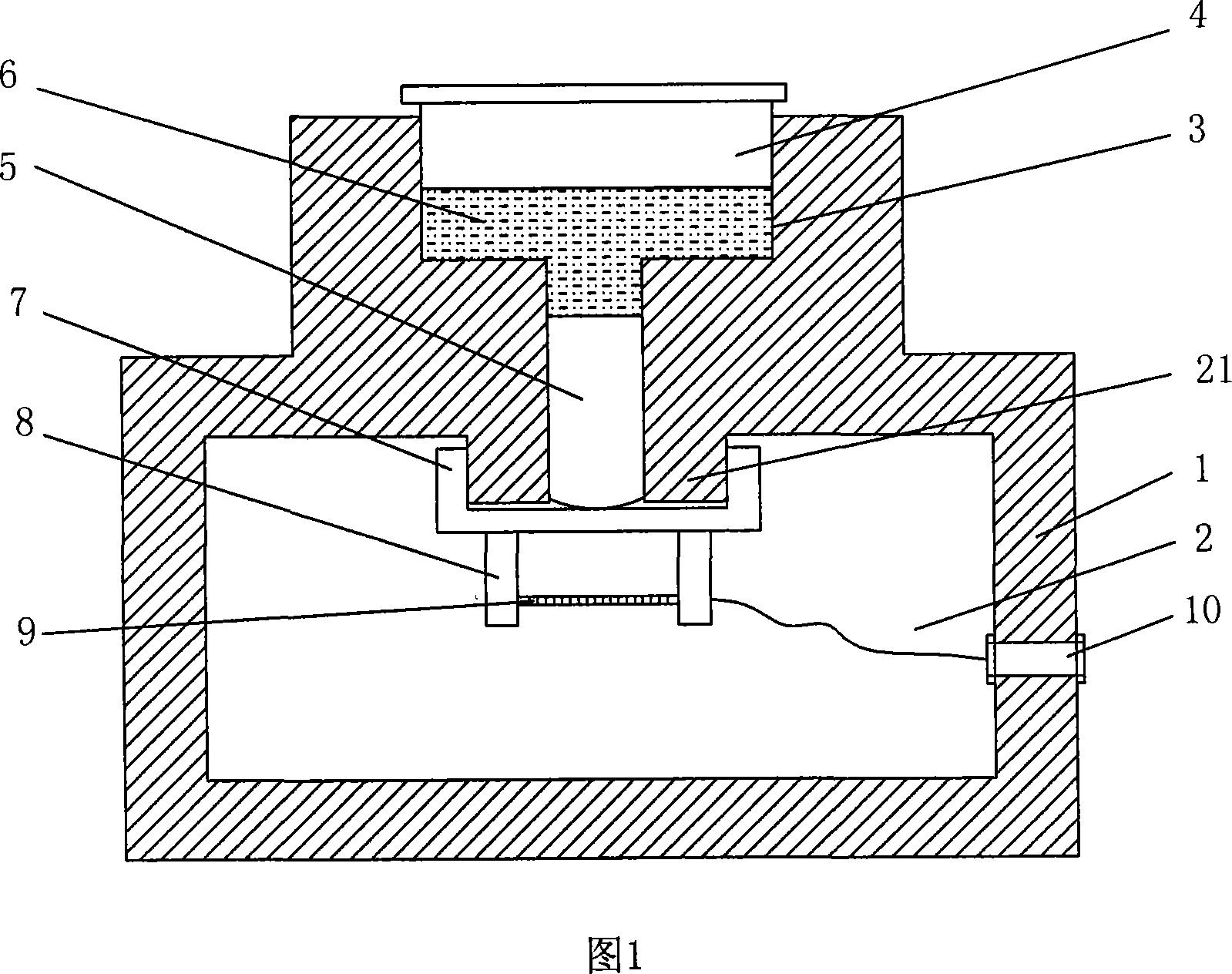
[0019] The present invention will be described in further detail below in conjunction with accompanying drawing, as shown in Figure 1, make a kind of piston-liquid-piston mechanical structure of fixed fiber grating sensing part, this mechanical structure comprises base 1, has cavity in base 1 Chamber 2, the upper part of the base 1 is provided with a stepped hole 3 communicating with the chamber 2, an upper piston 4 and a lower piston 5 are arranged in the stepped hole 3, the cross-sectional area of ​​the upper piston 4 is greater than that of the lower piston 5, The upper piston 4 and the lower piston 5 are filled with hydraulic oil 6, the lower end of the lower piston 5 is spherical, the top surface of the chamber 2 is centered on the central axis of the stepped hole 3, and protrudes downward to form a boss 21, the boss 21 is sleeved with a cylindrical elastic membrane 7, and the lower end of the lower piston 5 can be in contact with the elastic mold 7; the optical fiber grat...


PUM


Abstract

The present invention discloses one kind of pressure-measuring fiber grating process and device. After linear conversion of the measured force in a 'piston-liquid-piston' converter in the conversion ratio equal to the upper and the lower piston area ratio, the converted force is transmitted by the lower piston to the fiber grating with relatively small measuring range. The change in force causes the axial strain in the fiber grating, and change of fiber grating in parameters, including Bragg wavelength. After the mathematic model between the pressure and the central wavelength of the grating, measuring the wavelength can obtain the corresponding pressure. The present invention has the advantages of great measurement range, high precision, etc.

Description

technical field [0001] The invention relates to a mine pressure detection instrument, in particular to a mine pressure detection instrument with a large range and high precision. Background technique [0002] In the process of coal mining, the mechanical balance between rock mass and coal seam is destroyed, and "mine pressure" is formed around the mining face, also known as "roof pressure". The roof accident is the collapse of the roadway or the working face due to the collapse of the support under the pressure of the roof, which can easily cause casualties. The number of casualties caused by roof accidents accounts for about one-third of the number of casualties in coal mine production accidents in my country, and ranks first in excess of the number of deaths in gas accidents. At present, the main instruments used for mine pressure detection can be divided into mechanical type, hydraulic type, resistance strain type, vibrating wire type, etc. according to their working pri...

Claims


Application Information

Patent Timeline
IPC IPC(8): G01L1/24G01J3/18
Inventor 曹茂永李丽君孙农亮李晶范迪梁慧斌
Owner SHANDONG UNIV OF SCI & TECH
Learn More