Automatic measuring equipment for volume density of ceramic test sample

An automatic measurement and tile technology, applied in the direction of material analysis by measuring buoyancy, can solve problems such as complex structures

Inactive Publication Date: 2007-10-03
OURODIT
View PDF1 Cites 6 Cited by
  • Summary
  • Abstract
  • Description
  • Claims
  • Application Information

AI Technical Summary

Problems solved by technology

However, this known device has a complex structure

Method used


Image

  • Automatic measuring equipment for volume density of ceramic test sample
  • Automatic measuring equipment for volume density of ceramic test sample
  • Automatic measuring equipment for volume density of ceramic test sample

Examples


Embodiment Construction

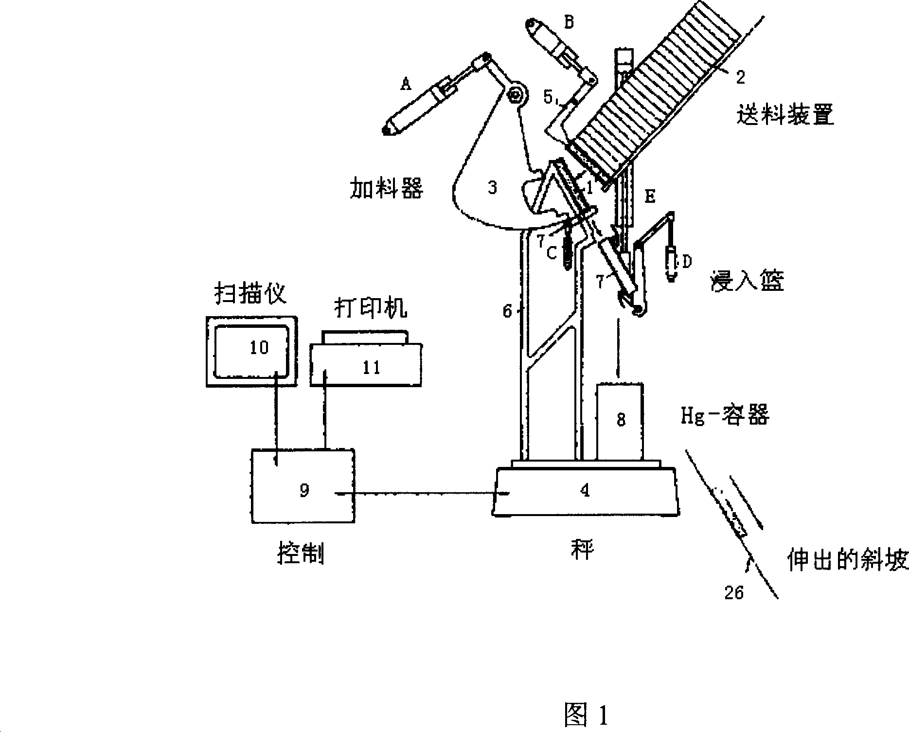
[0017] The device shown in Figure 1 is capable of determining the density of a sample and determining the density distribution in the following manner:

[0018] The first test sample 1 is transferred from the feeding device 2 onto the scale 4 by a transfer mechanism comprising a swivel arm 3 and actuated by a hydraulic or pneumatic cylinder A. Stopper 5 holds the other test samples in the feeder. The stand 6 on the scale provides the best position for the test sample on the scale. Scale 4 is used to determine the weight of the test sample. After weighing, a further conveyor mechanism 7 comprising baskets for picking up test samples dips the test sample 1 into a container 8 containing pure liquid mercury. This container 8 is preferably placed on the same scale 4 used to determine the weight of the test sample.

[0019] When the test sample is immersed in the mercury and the mercury is at rest, the scale 4 measures the buoyancy of the submerged basket with the test sample in ...


PUM


Abstract

The present invention relates to one kind of automatic equipment for measuring the bulk density of raw ceramic tile, and the equipment has simple structure and can detect the density distribution of raw ceramic tile quickly. The equipment includes one feeder for loading ceramic tile sample, one balance for measuring the sample weight, one first conveying mechanism to convey the sample onto the balance, one second conveying mechanism to convey the sample into one mercury container on the balance, one circuit connected to the balance, one display screen and/or one printer, and software of equipment operation and density value calculation.

Description

technical field [0001] The invention relates to an automatic measuring device, in particular to an automatic measuring device for the volume density of a green ceramic tile test piece. Background technique [0002] Ceramic tiles are usually formed by high-pressure compression in a mould, from slightly moist (moisture content about 5-7%) ceramic particles. After the raw tiles are dried, they are fired at high temperature. Improper filling of the press mold as well as tolerances in the pressing tool can result in uneven density of the pressed green tile. [0003] However, differences in the density distribution of green tiles can cause problems in subsequent tile processing steps. These problems may be of a different nature and may occur during processes such as drying, glazing and firing. In particular, these problems lead to defective products such as surface deformation during firing due to differences in shrinkage. [0004] To avoid or reduce these problems, it is ofte...

Claims


Application Information

Patent Timeline
Patent Type & Authority Applications(China)
IPC IPC(8): G01N9/08
Inventor 迪特里希・F・恩格尔曼
Owner OURODIT
Why Eureka
Try Eureka