Diffraction device

A diffraction element and diffraction pattern technology, applied in the field of diffraction elements, can solve the problems of high production cost, difficulty in making diffraction elements, fluctuations in diffraction efficiency, etc., and achieve the effect of less wavelength dependence

Inactive Publication Date: 2007-10-03
FUJINON SANO
View PDF1 Cites 11 Cited by
  • Summary
  • Abstract
  • Description
  • Claims
  • Application Information

AI Technical Summary

Problems solved by technology

That is to say, if such adjustment items are not fully performed, the diffraction efficiency will fluctuate
On the contrary, if the strictness of various adjustment items is pursued, the production of diffraction elements will be extremely difficult, and the production cost will become a big problem.

Method used


Image

  • Diffraction device
  • Diffraction device
  • Diffraction device

Examples


Embodiment Construction

[0032] A. Description of the diffraction element of the present invention

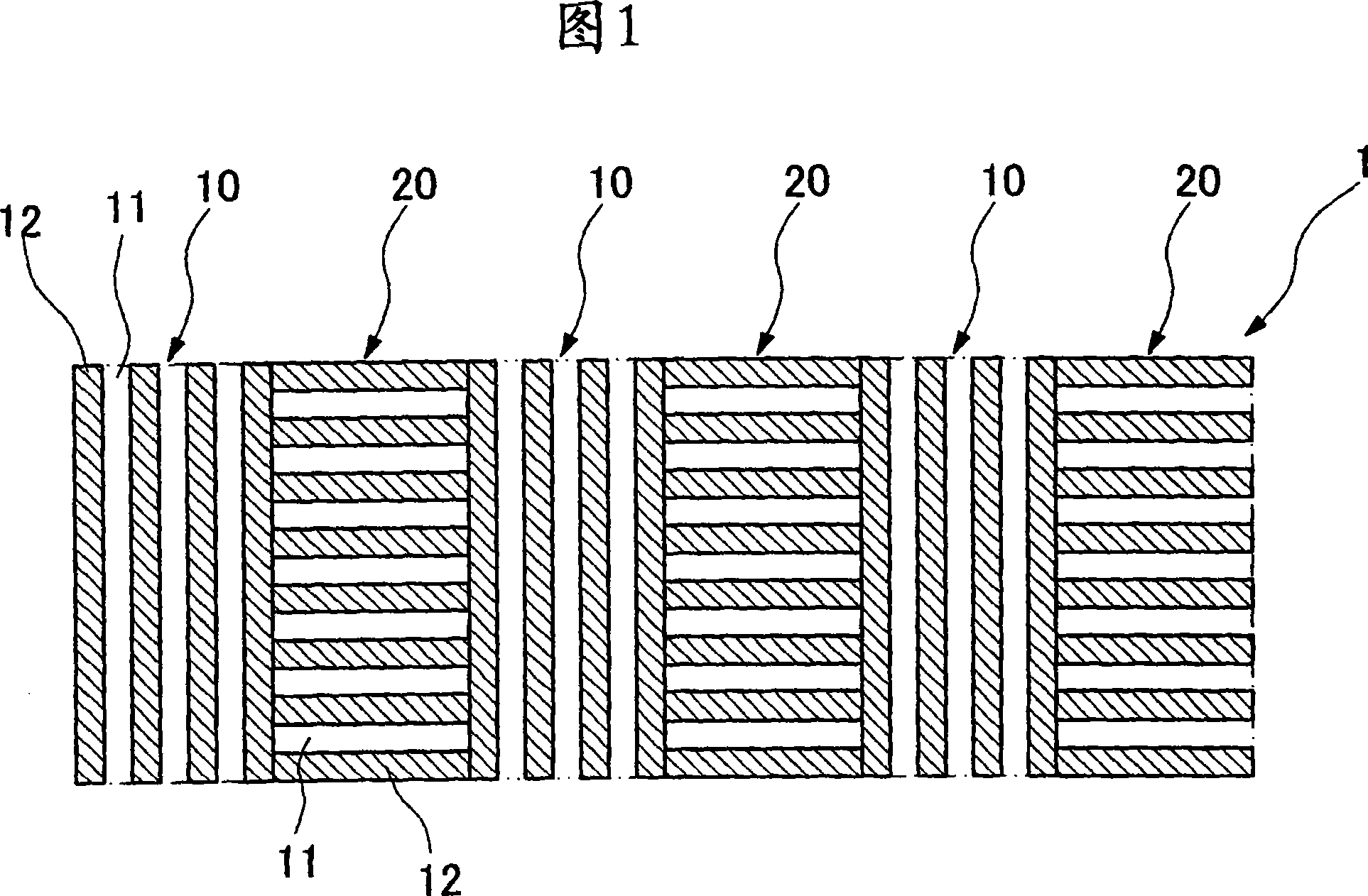
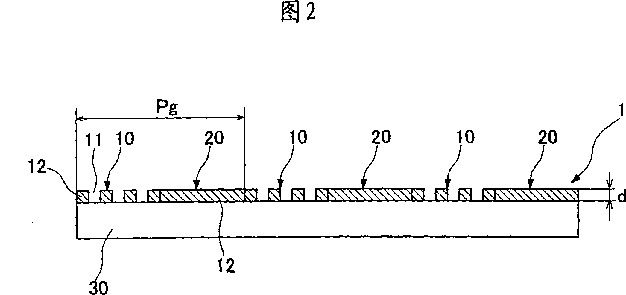
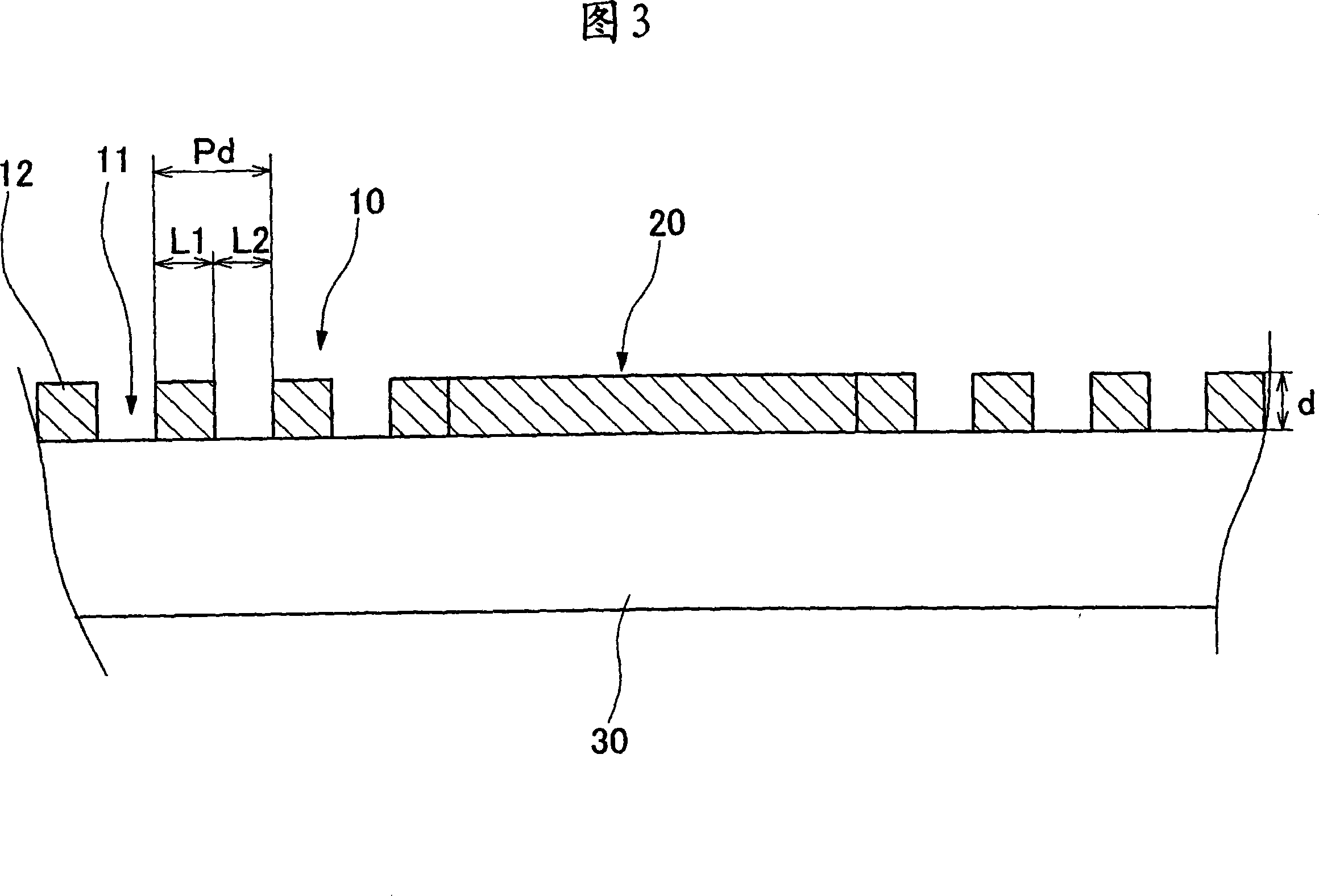
[0033] Embodiments of the present invention will be described below with reference to the accompanying drawings. As shown in FIGS. 1 and 2 , the first phase difference region 10 and the second phase difference region 20 of the diffraction element 1 of the present invention are formed on one side of a transparent substrate 30 such as a glass substrate. As shown in FIG. 1 , the first phase difference regions 10 and the second phase difference regions 20 are arranged in a periodic structure alternately. In the first phase difference region 10 and the second phase difference region 20 , as shown in FIG. 3 , a concave-convex structure with a fine pitch is formed. Such a micro-pitch concave-convex structure is formed by duplicating the concave-convex structure on resin or the like or by digging grooves on the transparent substrate 30 itself. Accordingly, the concave portion (below as concave portion 11) of...


PUM


Abstract

To provide a diffraction element having no wavelength dependency without using a special liquid crystal. In the diffraction element 1 for diffracting incident light, a plurality of first and second phase difference regions 10 and 20 for diffracting incident light are alternately arranged to form a diffraction pattern on a transparent substrate 30. A plurality of fine projecting and recessed structures are arranged in the first and the second phase difference regions 10 and 20 in nano order at a pitch interval shorter than the shortest wavelength of a plurality of wavelength regions for making phase differences of a plurality of wavelengths of incident light even. The fine projecting and recessed structures of the first phase difference region 10 and the fine projecting and recessed structures of the second phase difference region 20 are orthogonal to each other. Phase differences are made even by the fine projecting and recessed structures in the nano order and a diffraction function having diffraction efficiency nearly free from wavelength dependency can be exhibited by the diffraction pattern.

Description

technical field [0001] The present invention relates to a diffraction element that diffracts incident light, and particularly to a diffraction element that is less dependent on wavelength. Background technique [0002] Among the optical elements, there is a diffraction element that diffracts incident light, and the diffraction element can be used, for example, in an optical pickup or the like. The optical pickup can use the light emitted by the light source not only as an optical signal but also as a focus error detection signal and a tracking error detection signal. In this way, the diffraction element diffracts the signal light as 0th-order light, and diffracts the focus error detection signal and tracking error detection signal as ±1st-order light among incident light. For this reason, the diffraction element adopts a structure in which a concave-convex structure is formed on a glass substrate at the micron level. [0003] However, optical pickups in recent years are be...

Claims


Application Information

Patent Timeline
Patent Type & Authority Applications(China)
IPC IPC(8): G02B5/18
CPCG02B5/1809
Inventor 川村宜司仓桥肇
Owner FUJINON SANO
Why Eureka
Try Eureka