Zero-voltage-switching DC-DC converters with synchronous rectifiers

A synchronous rectifier, DC-DC technology, applied in the direction of converting equipment without intermediate conversion to AC, converting DC power input into DC power output, adjusting electrical variables, etc., can solve problems such as not eliminating diode reverse recovery and weakening

Active Publication Date: 2007-10-03
ASTEC INT LTD
View PDF0 Cites 43 Cited by
  • Summary
  • Abstract
  • Description
  • Claims
  • Application Information

AI Technical Summary

Problems solved by technology

However, these techniques only provide a compromise solution since the reverse recovery of the diode is weakened rather than eliminated

Method used


Image

  • Zero-voltage-switching DC-DC converters with synchronous rectifiers
  • Zero-voltage-switching DC-DC converters with synchronous rectifiers
  • Zero-voltage-switching DC-DC converters with synchronous rectifiers

Examples


Embodiment Construction

[0032] The following description is merely exemplary in nature and is not intended to limit the disclosure, application, or uses.

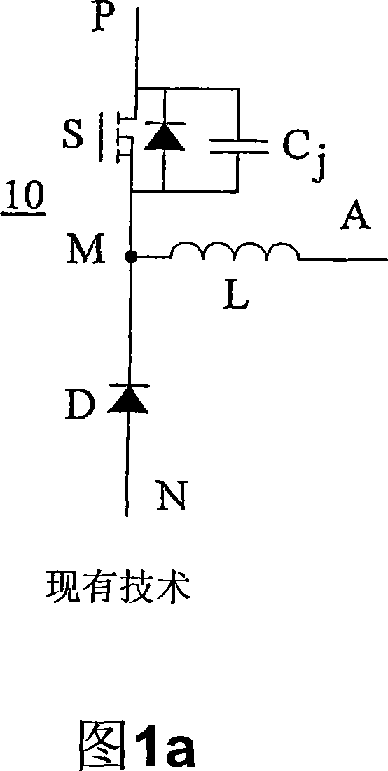
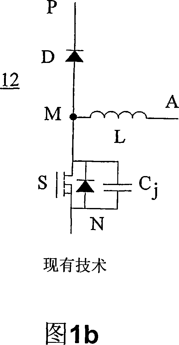
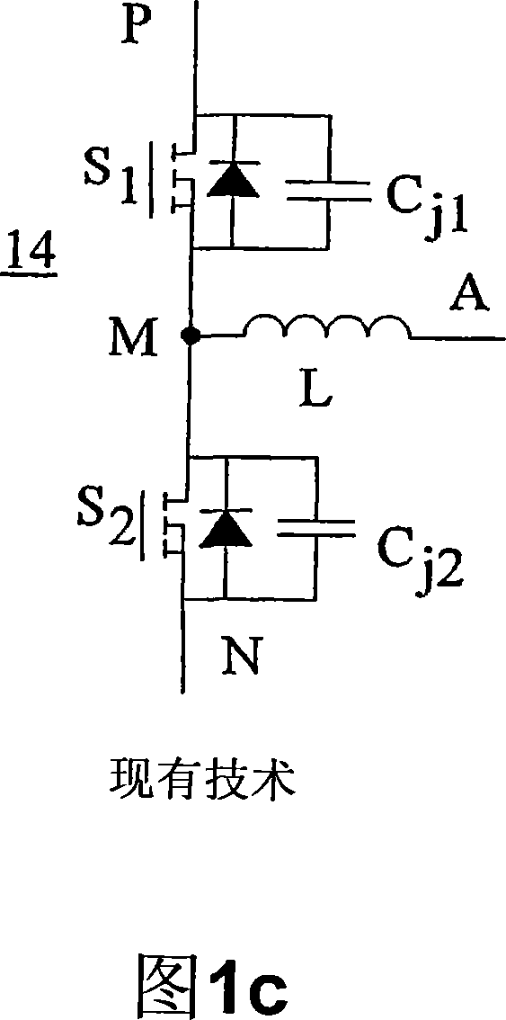
[0033] In the active resonant tank (ART) cell of the present disclosure, the body diode of the SR does not carry current when the SR is off, thus saving body diode conduction losses and eliminating switching and ringing associated with reverse recovery Loss (ringing loss). In one aspect of the present disclosure, an ART unit consists of a network comprising an LC resonant tank and active switches. Basically, before the main switch is turned on, the energy stored in the tank capacitance is transferred through the resonant inductor to discharge the junction capacitance of the main switch, so that the main switch is turned on with ZVS. In subsequent intervals, the ART unit is reloaded resonantly. Since the energy transfer occurs only during the switching transitions of the switches, the conduction losses dissipated in the resonant tank are limited....


PUM


Abstract

A DC-DC converter includes an inductor, a synchronous rectifier (SR) connected to the inductor, and an active switch connected to the inductor and the SR. An active resonant tank (ART) cell is connected to the SR or a transformer in parallel such that a resonant capacitor of the ART cell is charged through the active switch and discharged through the synchronous rectifier so that during a switch transition period energy is pumped out of the resonant capacitor by activating the ART cell to eliminate reverse recovery switching loss and achieve Zero Voltage Switching (ZVS).

Description

[0001] Cross References to Related Applications [0002] This application claims priority to US Provisional Application No. 60 / 788,594, filed March 31, 2006, the entire disclosure of which is incorporated herein by reference. technical field [0003] The present disclosure relates to dc-dc converters, and more particularly to zero voltage switching converters using synchronous rectification. Background technique [0004] The statements in this section merely provide background information related to the present disclosure and may not constitute prior art. [0005] In low output voltage dc-dc converters, synchronous rectifiers (SRs) are widely used to reduce rectifier conduction losses and improve converter efficiency. However, during the transition of the switch, since the voltage drop across the SR body diode is much higher than in the switch, the parasitic body diode of the SR inevitably carries a load current that reduces the conversion efficiency. In addition, the reve...

Claims


Application Information

Patent Timeline
Patent Type & Authority Applications(China)
IPC IPC(8): H02M3/10H02M3/155
CPCH02M3/33592H02M3/156H02M3/1588H02M2001/0051Y02B70/1425Y02B70/1433Y02B70/1466Y02B70/1475Y02B70/1491Y02B70/10H02M1/0051
Inventor H·毛
Owner ASTEC INT LTD
Why Eureka
Try Eureka