Light source device

A technology for a light source device and a reading device, which is applied in the directions of light source, electric light source, electric light source, etc., can solve the problems such as the inability to apply discharge lamps, the limitation of discharge lamps, and the inability to update light source devices.

Active Publication Date: 2007-10-03
ORC MFG
View PDF1 Cites 4 Cited by
  • Summary
  • Abstract
  • Description
  • Claims
  • Application Information

AI Technical Summary

Problems solved by technology

[0017] According to such a lamp / holding unit, only discharge lamps of specifications registered in the light source device can be applied, but discharge lamps of newly developed specifications cannot be applied.
In addition, since the setting of the light source device cannot be updated, there is a problem that the discharge lamps that can be used are limited.

Method used


Image

  • Light source device
  • Light source device
  • Light source device

Examples


no. 1 approach

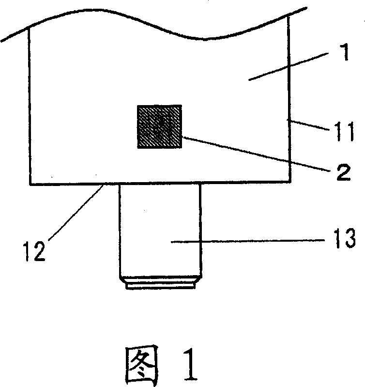
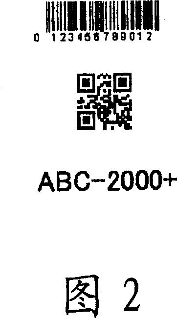
[0047] The first embodiment of the present invention is constituted such that a lamp / data display portion 2 is provided on the side of the cylindrical base portion 11 of the cap 1 of the discharge lamp, and the data displayed by the lamp / data display portion 2 is read by an optical reading device. Lamp / data (attributes and specifications of the discharge lamp) is used to import the attributes and setting specifications of the installed discharge lamp into the light source device.

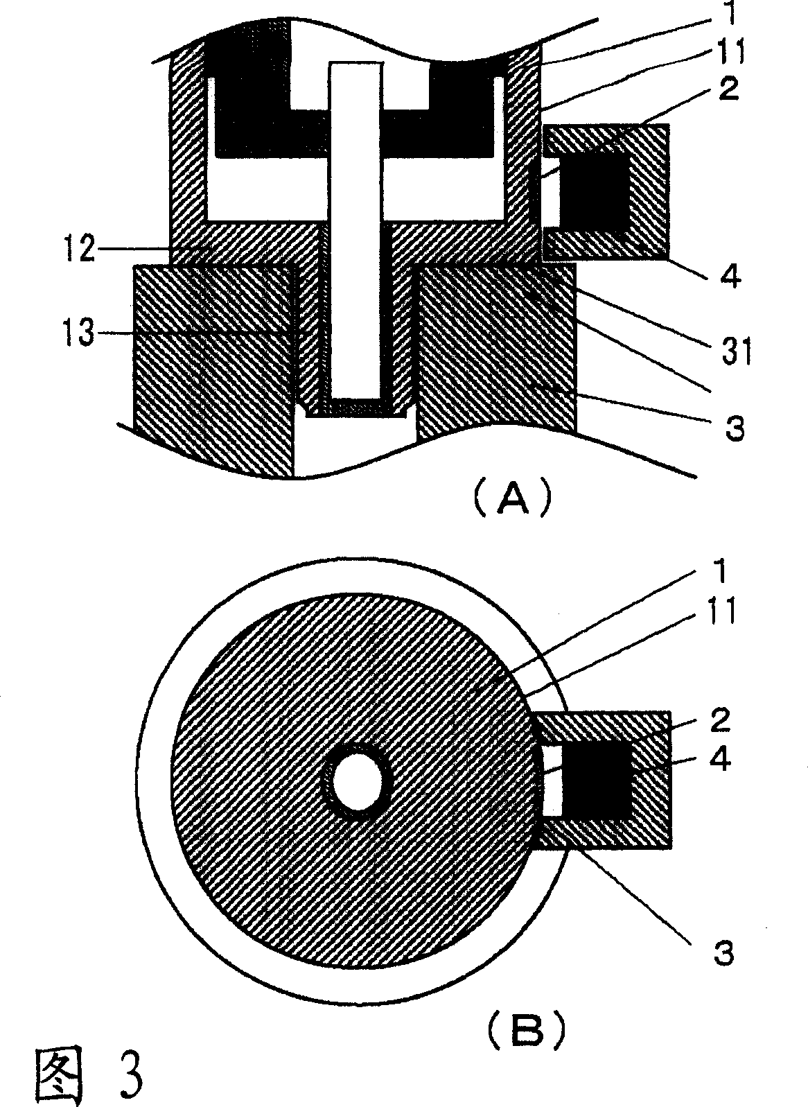
[0048] As shown in FIG. 1 , a lamp / data display unit 2 displaying properties and setting specifications of the discharge lamp is formed on a side surface of a large-diameter cylindrical base 11 of the base 1 . And as shown in Figure 3, it is configured that when the small-diameter protruding portion 13 of the lamp cap 1 is inserted into the hole 32 opened on the abutting surface 31 of the lamp cap holder 3 of the light source device to install the discharge lamp, the lamp / The data display unit 2 fa...

no. 2 approach

[0064] As shown in the longitudinal sectional view of FIG. 5 , in the second embodiment of the light source device of the present invention, a lamp / data display part 2 is provided under the cylindrical base 11 of the lamp cap of the discharge lamp, and a lamp / data display part 2 is arranged on the abutting surface of the lamp cap 3 . 31 is provided with a reading device 4 for reading the data of the lamp / data display unit 2 . By integrating the reading device 4 with the base 3 in this way, the structure of the light source device can be simplified.

no. 3 approach

[0066] As shown in the longitudinal sectional view of Figure 6, the third embodiment of the light source device of the present invention is provided with a lamp / data display part 2 on the disc-shaped contact surface 12 of the lamp cap of the discharge lamp, and on the lamp cap holder 3 of the light source device. In the concave portion 33 formed on the contact surface 31, the reading device 4 for reading the data of the lamp / data display part 2 of the discharge lamp is provided via the light-shielding space. With such a configuration, the size of the base holder 3 does not change, and the size of the device can be reduced.


PUM


Abstract

The invention provides a light source device. The said light source device automatically judges whether the discharge lamp mounted on the light source device is proper discharge lamp , if it is the proper discharge lamp, the service mode and service history of the discharge lamp is administered. The discharge lamp comprises: discharge lamp with lamp head (1) and lamp/data displaying part (2) for displaying the lamp/data associated with discharge lamp on the lamp head (1), the said lamp head (1) composed of cylindrical base (11)of large diameter by sealing one end using disck shaped abutting surface (12) and projection (13) of large diameter by interpenetrating the centre of the disck shaped abutting surface and coaxial implanting ; and lamp head seat (3) for holding the lamp head of the discharge lamp and performing power on, with a reading device on the lamp head seat (3) for reading the date of the lamp/data displaying part (2).

Description

technical field [0001] The present invention relates to a light source device having a discharge lamp for exposing and generating ultraviolet rays in the manufacturing process of a semiconductor device (IC), a liquid crystal display panel (LCD), a printed wiring board (PCB), etc. A lamp data display unit that displays the attributes and setting specifications of each discharge lamp, and is a light source device that can manage the usage status and history of the discharge lamps by reading the attributes and setting specifications. Background technique [0002] As shown in FIG. 18, the discharge lamp used in the conventional light source device is composed of the following parts: a quartz bulb 5 composed of a spherical expansion part 51 and two closed tube parts 52; The anode 53 and the cathode 54, the inner guide rod 55 that supports and conducts electricity to these anode 53 and the cathode 54, the outer guide rod 56, and the inner guide rod 55 and the outer guide rod 56 ar...

Claims


Application Information

Patent Timeline
Patent Type & Authority Applications(China)
IPC IPC(8): H05B41/36H05B37/02F21Y101/00
CPCY02B20/42F21S2/005F21V19/00F21V23/00H05B47/00H05B47/10
Inventor 石锅荣彦屋木康彦安达伸雄
Owner ORC MFG
Why Eureka
Try Eureka