Anti-freezing pressure reducing device for natural gas

A pressure reducer and natural gas technology, which is applied in the field of balance valves, can solve the problems of increasing management workload and achieve low cost, improve environmental conditions, and overcome the effects of frosting and cooling

Inactive Publication Date: 2007-10-10
易会球
View PDF1 Cites 3 Cited by
  • Summary
  • Abstract
  • Description
  • Claims
  • Application Information

AI Technical Summary

Problems solved by technology

It is also possible without incre

Method used


Image

  • Anti-freezing pressure reducing device for natural gas
  • Anti-freezing pressure reducing device for natural gas

Examples


Embodiment Construction

[0025] Further description will be given below in conjunction with the implementation examples and accompanying drawings.

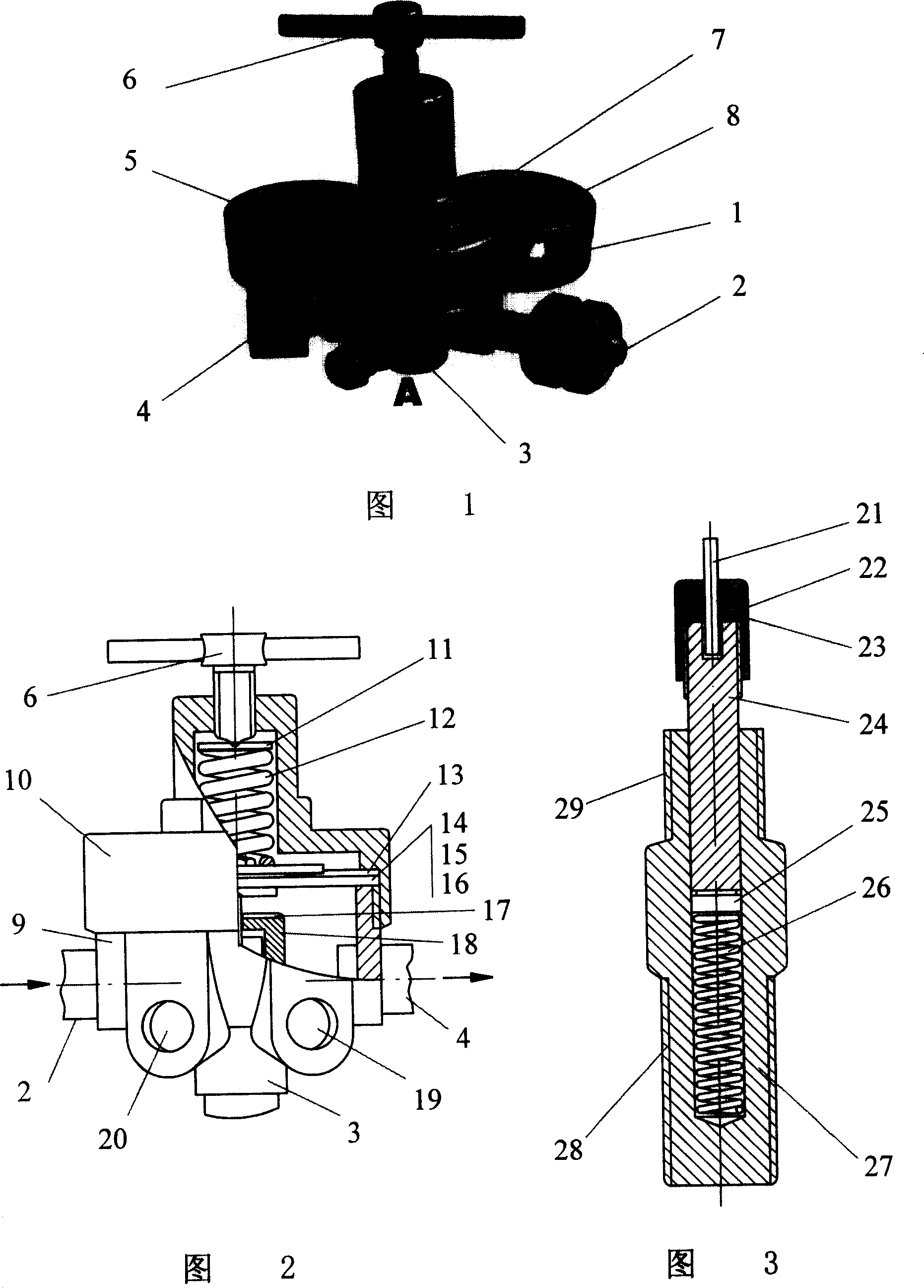
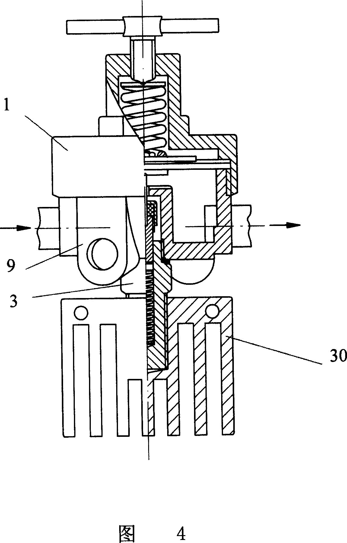
[0026] As shown in Figure 1: Natural gas and gas pressure reducing valves are often used in pipelines, gas cylinders and busbars. It is mainly composed of valve body 1, air inlet and outlet ports 2 and 4, air pressure gauges 5 and 8, regulating device 6 and thimble device 3. The thimble device is located at part A, and the thimble and pressure spring are directly installed on the valve body wall by plugging screws. Due to the compact structure, the influence of temperature drop during operation is great, and the pressure change when single-stage is used is small, and 2 to 3 more stages are needed to achieve the decompression target from 25MPa to 0.8MPa. The air intake hole and the diaphragm assembly on the air intake platform can seal off the air during adjustment. When used in a single stage with a large load, it will be frozen soon. The 7th, communic...


PUM

PropertyMeasurementUnit
Thicknessaaaaaaaaaa

Abstract

An anti-freezing pressure release valve of natural gas consists of valve body, air inlet and outlet, gas pressure meter interface, diaphragm set, regulation unit and center unit. It is featured as setting center unit at bottom of valve body to be center unit being connected long, externally arranging operation spring of center unit in socket sleeve and setting heat conduction component used for radiating heat at down end of socket sleeve.

Description

technical field [0001] The present invention relates to balancing valves. Specifically, it is a balance valve device used for decompression of compressed natural gas and adjustable output pressure. Background technique [0002] Natural gas is compressed and pressurized during transportation. The high-pressure gas at the source end is as high as 20MPa-25MPa, and the output pressure of the gas entering the pressure reducing valve at the user end is 0.3MPa-0.8MPa. Due to the existence of pressure difference, frost will form due to diffusion, resulting in a sharp drop in the temperature in the low-pressure gas chamber. The greater the pressure difference, the more significant the cooling phenomenon and the more serious the consequences. In the light case, the gas pressure and flow measurement will be inaccurate. In the severe case, the thimble device will fail, and the balance valve will fail, so that the pipeline will be in an abnormal state o...

Claims


Application Information

Patent Timeline
IPC IPC(8): F16K17/04F16K49/00G05D16/06
Inventor 易会球
Owner 易会球
Why Eureka
Try Eureka