
Method and equipment for continuous smelting of lead sulphide concentrate
A lead sulfide and concentrate technology, applied in the chemical industry, climate sustainability, sulfur trioxide/sulfuric acid, etc., can solve the problems of workers' health hazards, underutilization, and poor industrial hygiene conditions, and achieve SO2 The effect of small concentration fluctuation, obvious energy saving effect and low operating cost
Patent Information
- Authority / Receiving Office
- CN · China
- Patent Type
- Applications(China)
- Current Assignee / Owner
- Publication Date
- 2008-06-18
Smart Images
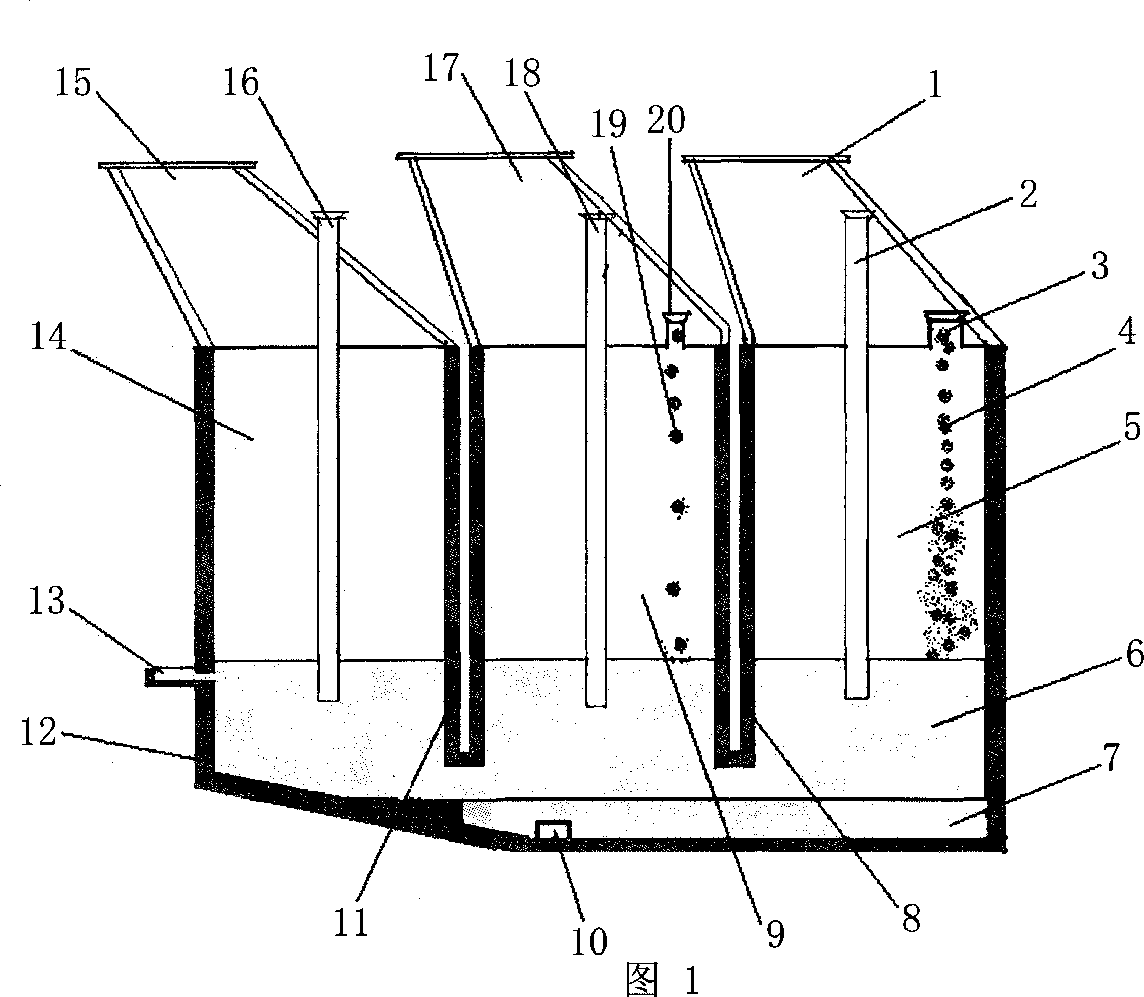
Figure 1
Abstract
Description
technical field
[0001] The invention relates to non-ferrous metal metallurgical technology, in particular to the pyrometallurgy of lead sulfide concentrate and the special equipment used to realize the process. Background technique
[0002] Lead smelting methods can be summarized into two categories: traditional lead smelting method and direct lead smelting method. The traditional lead smelting method is the sintering machine-blast furnace smelting method; the direct lead smelting method is to cancel the sintering process of the lead sulfide concentrate, and the raw concentrate is directly smelted in the furnace. For many years, the traditional method has been the main production method of lead. However, with the continuous improvement of human awareness and requirements for environmental protection and energy conservation, the shortcomings of the traditional lead smelting method have become increasingly prominent. Many lead smelters in the world have gradually adopted direc...
Examples
Embodiment
[0019] Referring to Fig. 1, in the liquid slag layer 6 of the molten pool of this lead sulfide concentrate continuous smelting furnace, partition walls 8 and 11 are arranged above the smelting space, and the part and the upper space of the liquid slag layer 6 are separated into mutually disconnected oxidation zones. Area 5, reduction area 9, and fuming area 14 are three areas, and the top of each area has its own flue gas outlet, that is, flue gas outlet 1 in the oxidation area, flue gas outlet 15 in the fuming area, flue gas outlet 17 in the reduction area, Each is equipped with spray guns 2, 16 and 18, the smelting material inlet 3 is set at the top of the oxidation zone 5, a siphon discharge port 10 is provided at the crude lead layer 7 at the bottom of the furnace body, and the slag discharge port 13 is provided at the fuming zone 14 6 places of the liquid slag layer. The fuming zone 14 at the bottom of the furnace body of the present invention is provided with a slope, so...