Scientific instrument work state monitoring method based on control computer

A technology for controlling computers and scientific instruments, applied in the direction of registering/indicating machine work, computer control, instruments, etc., can solve problems such as difficult installation of devices, and achieve the effects of ensuring safety, easy installation and implementation, and flexible and convenient selection

Inactive Publication Date: 2007-10-10
JILIN UNIV
View PDF1 Cites 9 Cited by
  • Summary
  • Abstract
  • Description
  • Claims
  • Application Information

AI Technical Summary

Problems solved by technology

However, for some new modern scientific instruments whose working process is almost completely controlled by computer, many functi

Method used


Image

  • Scientific instrument work state monitoring method based on control computer
  • Scientific instrument work state monitoring method based on control computer
  • Scientific instrument work state monitoring method based on control computer

Examples


Example Embodiment

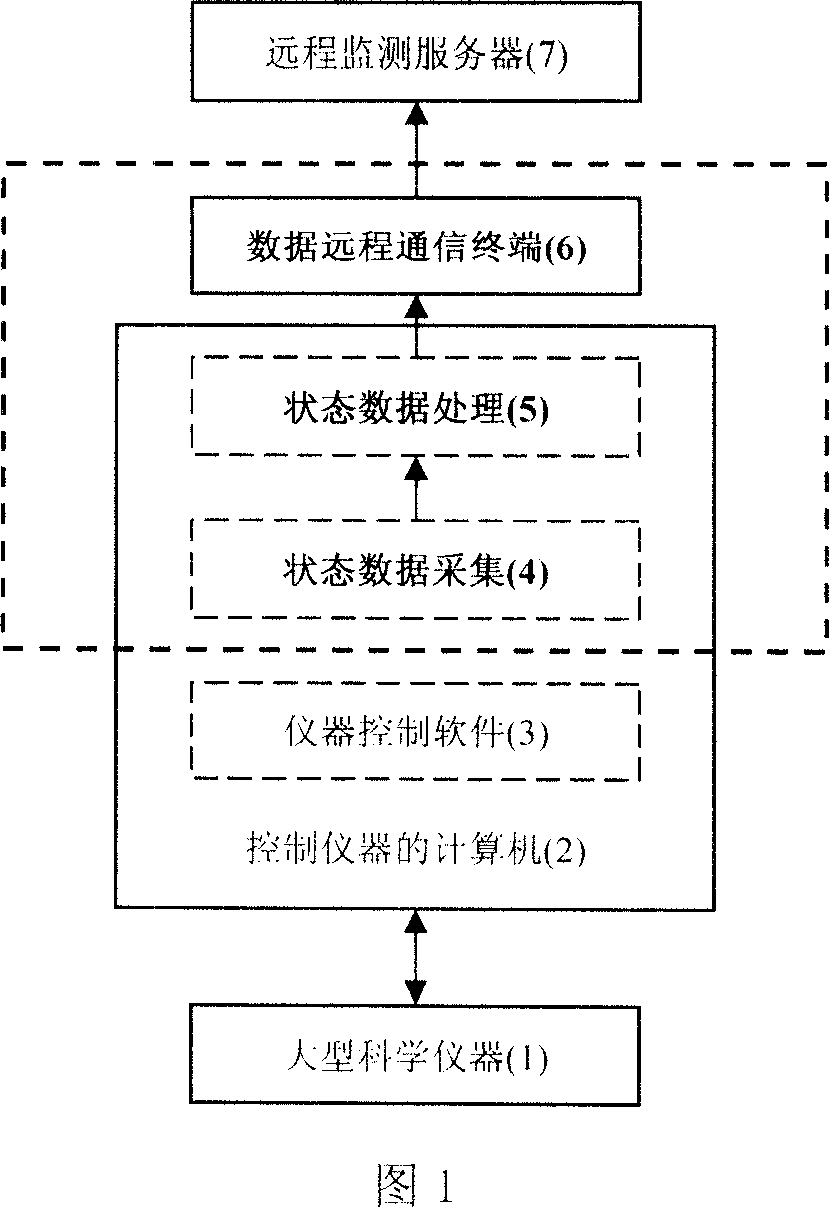
[0025] As shown in Figure 1, the remote monitoring method for the working status of large scientific instruments based on the control computer is composed of three parts: status data collection (4), status data processing (5), and data remote communication terminal (6). 4) and status data processing (5) are located in the computer (2) that controls the instrument. The working process of the large scientific instrument (1) is almost completely controlled by the instrument control software (3) located in the control computer (2). The status data processing (5) processes the data collected by the status data collection (4) and sends it to the data remote communication terminal (6), and the data remote communication terminal (6) sends it to the remote monitoring server (7). In this way, users can obtain real-time information about the working status of scientific instruments by accessing the monitoring server.
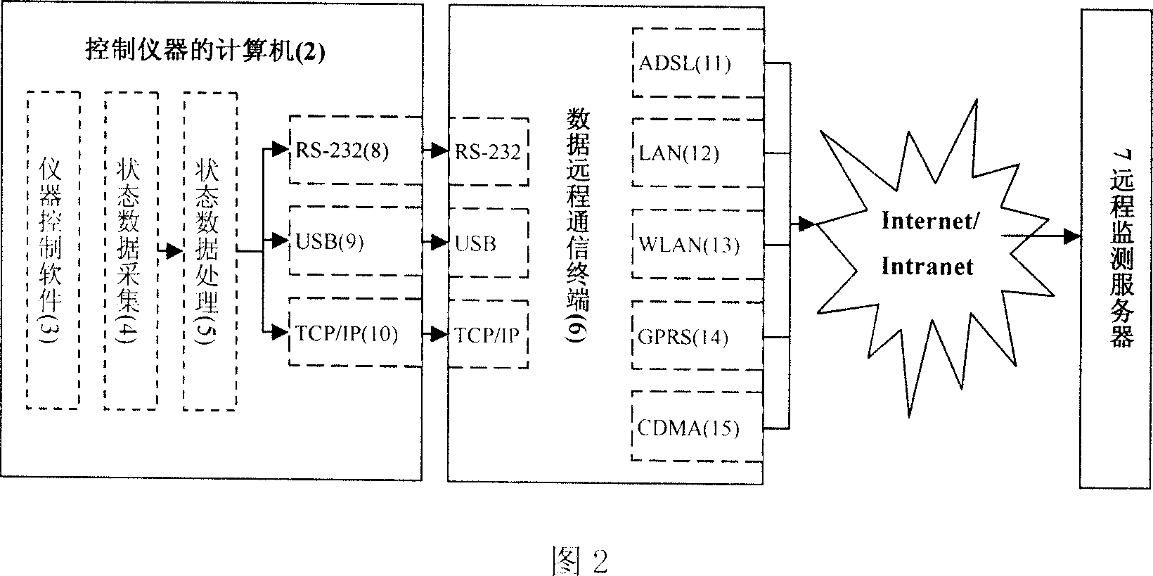
[0026] Refer to Figure 2. There are RS-232 (8), USB (9), TCP / IP (10) thre...


PUM


Abstract

The present invention relates to a scientific instrument working state monitoring method based on control computer. It is composed of three portions of sate data acquisition, state data processing and data telecommunication terminal. Said state data acquisition portion adopts a multimode combined detection method based on mouse keyboard hook, software interface characteristics, journal file and communication interface data flow. It is characterized by utilizing detection for control software and control computer to obtain working state of instrument. The state data processing portion is used for processing state data into unified format. The data telecommunication terminal can be used for sending data into remote monitoring server, and the communication mode of said data telecommunication terminal and control computer has RS-232, USB and TCP/IP, and the telecommunication mode includes ADSL, LAN, WLAN, GPRS and CDMA.

Description

technical field [0001] The invention relates to a method for monitoring the working state of a scientific instrument, in particular to a method for remote real-time monitoring of the working state of a large scientific instrument based on a control computer. Background technique [0002] Some existing scientific instruments can automatically record their working states such as excitation sources. One is through hardware devices such as code discs, such as the EMX-SM electronic probe of Shimadz Company, the MAT-251 stable isotope gas mass spectrometer of Thermo Finnigan Company, etc.; the other is through the control software of the instrument workstation, such as the JSM of JEOL Company -6700F cold field emission scanning electron microscope, etc. But they can only view data on site, do not support remote transmission of data, and cannot realize remote real-time monitoring of their working status. [0003] Some laboratory information management systems (LIMS) are connected...

Claims


Application Information

Patent Timeline
IPC IPC(8): G07C3/00G05B19/048G05B19/418
CPCY02P90/02
Inventor 田地王丰贵杨智君毛宏宇孙蕊杨红生陈璐孟祥玲关姗姗马骏骁李伟杨光乔艳明李春生邱春玲
Owner JILIN UNIV
Why Eureka
Try Eureka