Device for removing engine vibration and engine whose stroke characteriscts are variable

A vibration elimination and engine technology, which is applied in the direction of engine components, machines/engines, mechanical equipment, etc., can solve problems such as unavoidable engine enlargement, difficulty in simultaneously reducing engine secondary vibration, secondary vibration, and freedom limit

Inactive Publication Date: 2007-10-10
HONDA MOTOR CO LTD
View PDF6 Cites 24 Cited by
  • Summary
  • Abstract
  • Description
  • Claims
  • Application Information

AI Technical Summary

Problems solved by technology

[0020] Therefore, even if a secondary balance device is installed in such an engine to reduce secondary vibration, it is difficult to simultaneously reduce the secondary vibration when the engine is in a high compression ratio state and the secondary vibration when the engine is in a low compression ratio state. a question
[0021] In addition, in the multi-link reciprocating engine, it is actually difficult to achieve a connecting rod structure that can sufficiently reduce vibration within the limited volume of the crankcase. If priority is given to reducing vibration, there is a problem that the degree of freedom in the design of the connecting rod is greatly restricted, and the increase in size of the engine cannot be avoided.

Method used


Image

  • Device for removing engine vibration and engine whose stroke characteriscts are variable
  • Device for removing engine vibration and engine whose stroke characteriscts are variable
  • Device for removing engine vibration and engine whose stroke characteriscts are variable

Examples


Embodiment 1

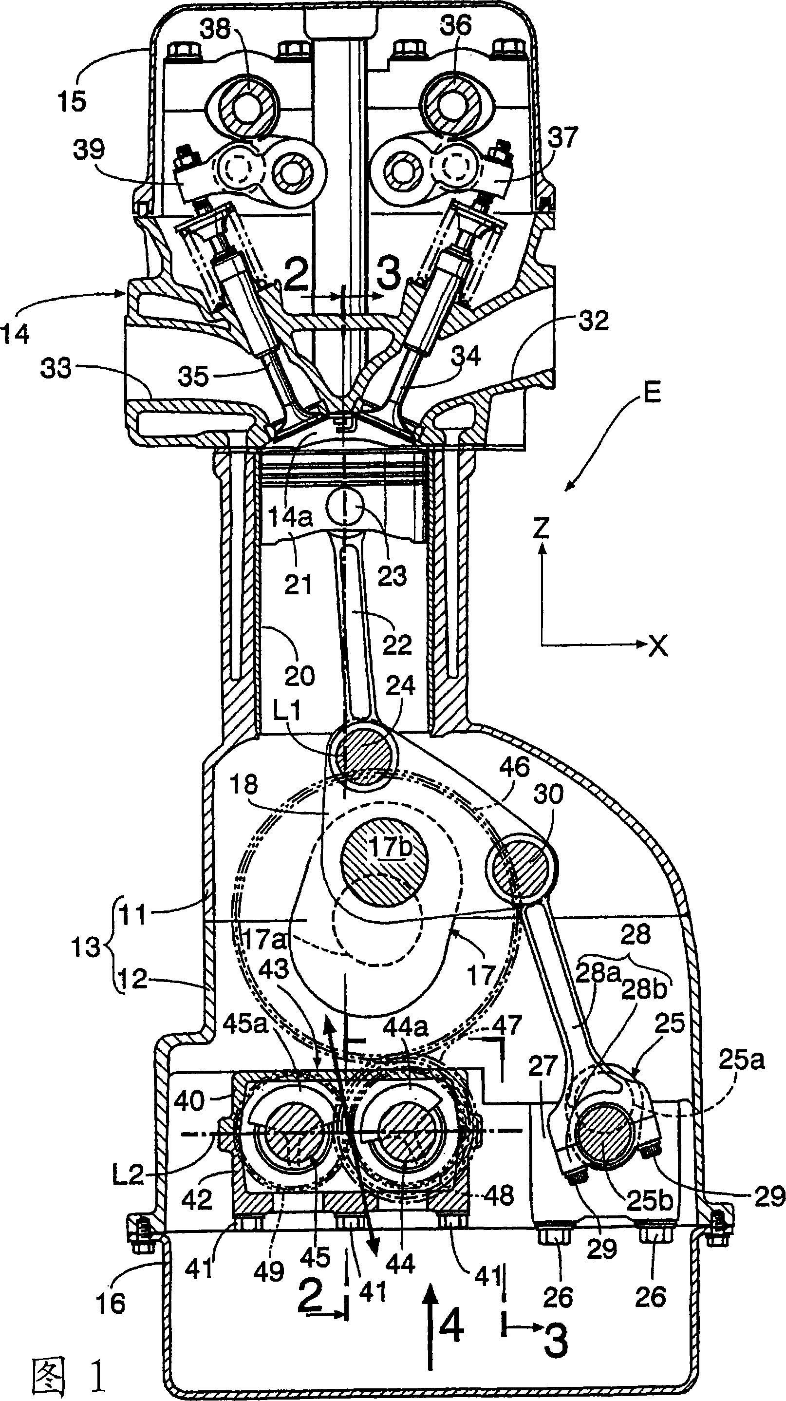
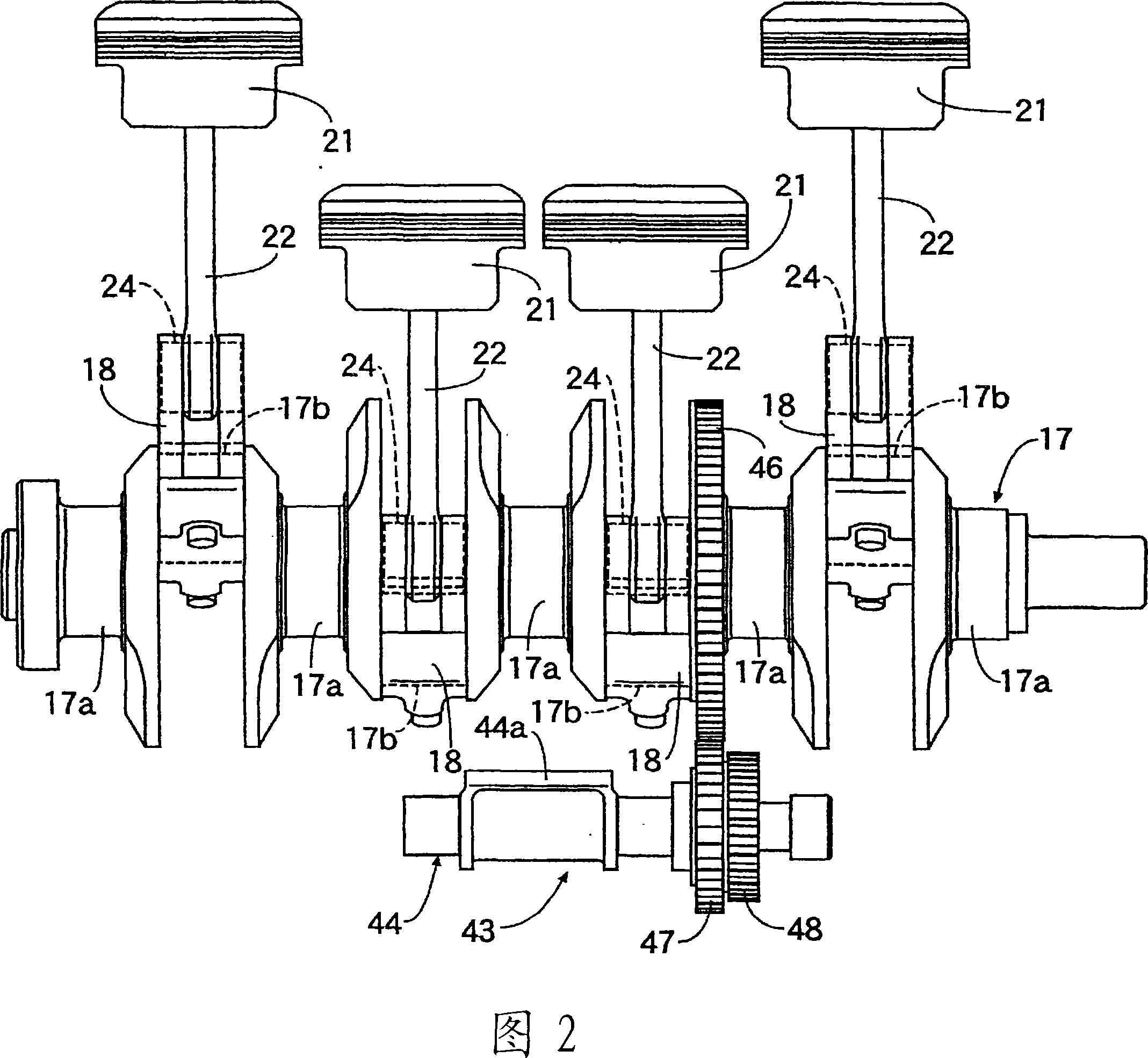
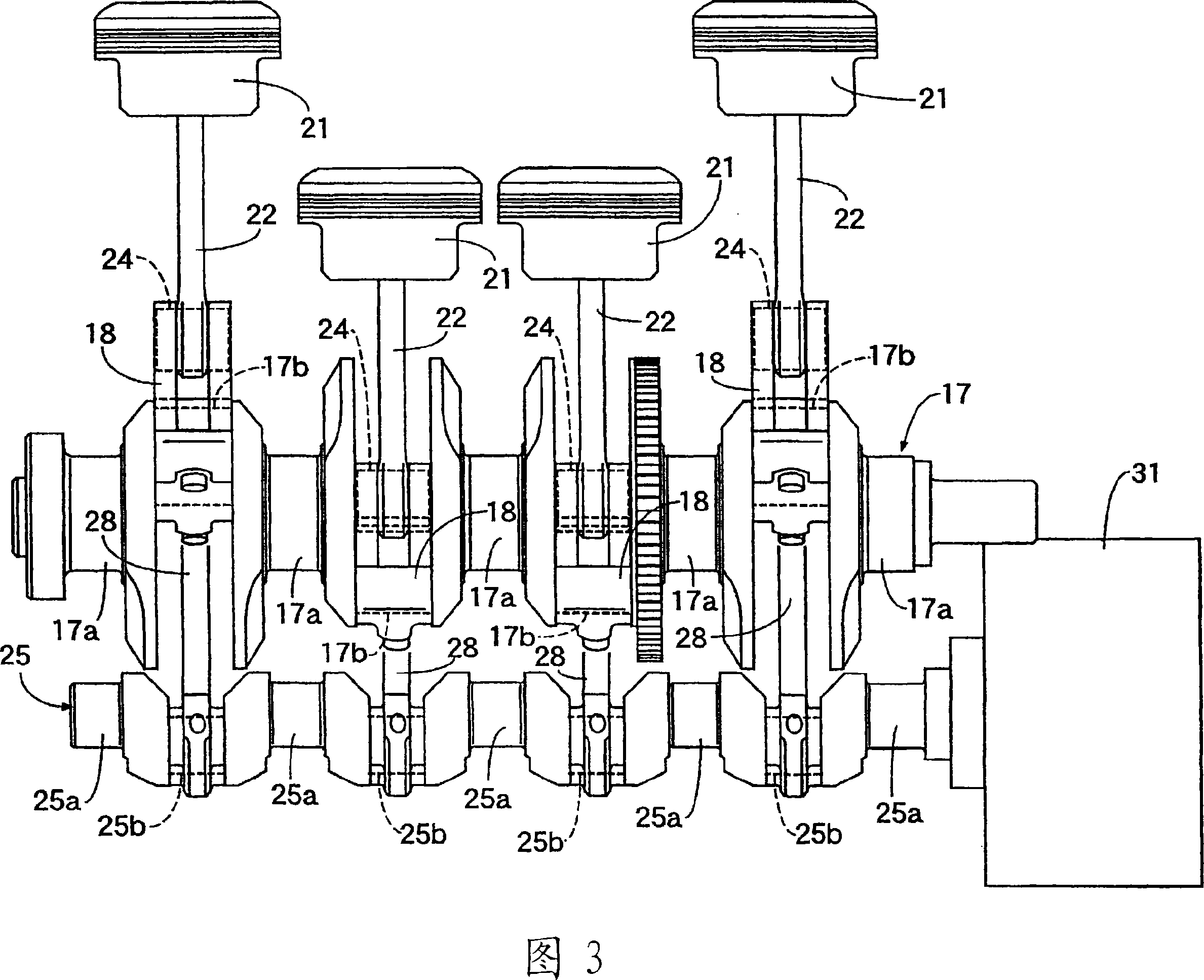
[0126] As shown in Figures 1 to 4, the variable compression ratio engine E is an example of a variable stroke characteristic engine that can change the position of the top dead center or bottom dead center of the piston by arranging a plurality of connecting rods. The engine E has an engine block 13 formed by combining a cylinder block 11 and a crankcase 12, a cylinder head 14 and a cylinder head cover 15 are connected to the upper part of the cylinder block 11, and an oil pan 16 is connected to the lower part of the crankcase 12. . The main journal 17a of the crankshaft 17 is rotatably supported on the interface between the cylinder block 11 and the crankcase 12, and the middle portion of the substantially triangular lower link 18 is rotatably supported on a crankpin journal eccentric from the main journal 17a. (pin journal) 17b.

[0127] The piston 21 is slidably fitted in the cylinder liner 20 provided in the cylinder block 11, the upper end of the upper link 22 (connectin...

Embodiment 2

[0144] Next, a second embodiment of the present invention will be described with reference to FIG. 10 .

[0145] The engine E of the first embodiment is arranged so that the cylinder axis L1 stands vertically, but the engine E of the second embodiment shown in FIG. 10 is arranged so that the cylinder axis L1 is inclined to the intake side by an angle θ. However, a straight line L2 connecting the centers of the first and second balance shafts 44 , 45 of the secondary balancer 43 extends in a horizontal direction parallel to the bottom surface of the oil pan 16 . The phases of the first and second counterweights 44a, 45a are set such that they are directed upwards in the vertical direction or downwards in the vertical direction at the same time, so that the direction of the exciting force generated by the secondary balancing device 43 (refer to arrow) becomes the vertical direction.

[0146] Since the cylinder axis L1 of the engine E is inclined by the angle θ with respect to t...

Embodiment 3

[0148] Next, a third embodiment of the present invention will be described with reference to FIG. 11 .

[0149] The engine E of the second embodiment shown in FIG. 10 is arranged such that the cylinder axis L1 is inclined to the intake side by an angle θ, but the engine E of the third embodiment shown in FIG. 11 is arranged so that the cylinder axis L1 is inclined to the exhaust side. . Since the positional relationship of the secondary balancer 43 with respect to the cylinder axis L1 is the same as that of the second embodiment, the straight line L2 connecting the centers of the first and second balance shafts 44, 45 is more inclined with respect to the vertical direction.

[0150] According to this third embodiment, not only can the vibration of the engine E be effectively eliminated as in the first and second embodiments, but also, compared with the second embodiment, the direction (X direction) of the engine block 13 width, but the size of the cylinder axis L1 direction (...


PUM


Abstract

A device for removing engine vibration, capable of effectively removing secondary vibration cause by reciprocation of a piston (21) of a multilink-type variable compression ratio engine (E). The secondary vibration can be removed even if the direction of the secondary vibration is inclined relative to the cylinder axis (L1), and the removal is made by inclining the direction (see the arrow direction) of vibration exciting force, produced by a secondary balancer device (43), so that it matches the direction of the secondary vibration. The secondary balancer device (43) is constructed by having balancer weights (44a, 45a) respectively supported by a pair of balancer shafts (44, 45) rotating in the directions opposite from each other. Displacing the phases of the balancer weights (44a, 45b) enables the direction of the produced vibration exciting force to be inclined so that it matches the direction of the secondary vibration of the engine (E).

Description

technical field [0001] The present invention relates to a vibration elimination device of an engine, which eliminates the vibration of the engine whose vibration direction is inclined relative to the axis of the cylinder through a balancing device. [0002] Furthermore, the present invention relates to an engine vibration canceling device having a variable stroke characteristic mechanism for changing the stroke characteristic of a piston and a balance device for reducing vibration accompanying engine operation, and further relates to a variable stroke characteristic mechanism for changing the stroke characteristic of a piston And the vibration canceling device of the engine of the secondary balance device that reduces the secondary vibration accompanying the reciprocating movement of the piston. [0003] Further, the present invention relates to a vibration canceling device for an engine including a variable stroke characteristic mechanism for changing the stroke characteristi...

Claims


Application Information

Patent Timeline
Patent Type & Authority Applications(China)
IPC IPC(8): F16F15/26F02B77/00F02B75/04F16F15/24F02B75/32
Inventor 江户宏一前鹤昭德生驹浩一矶和彦冈田义裕木下将一
Owner HONDA MOTOR CO LTD
Why Eureka
Try Eureka