Automobile accelerator over-force conversion braking device

A technology of brake device and conversion device, which is applied in the arrangement of power device control mechanism, foot-operated starting device, vehicle parts, etc., can solve the problems of the car rushing forward, and achieve sensitive and accurate action, convenient disassembly and assembly, and simple operation Effect

Inactive Publication Date: 2007-10-17
邓瑞祥
View PDF0 Cites 3 Cited by
  • Summary
  • Abstract
  • Description
  • Claims
  • Application Information

AI Technical Summary

Problems solved by technology

[0002] As we all know, at present, the accelerator and brake of the car are operated by the driver's right foot, and the pedals of the accelerator and brake are next to each other. Moreover, the accelerator pedal is lower than the brake pedal. When there is an emergency, the driver is easy to mistake the accelerator pedal for The brake pedal, after stepping hard to refuel, causes the car to rush forward and cause an accident. Sometimes, the driver does not lift the foot but only moves a distance, which is regarded as the brake pedal. In fact, the foot is under the brake pedal, and the inner side of the foot is still connected to the accelerator pedal. Contact, step hard or step on the accelerator pedal, the car rushes forward and causes accidents, especially for students who are just learning to drive, the above situations often occur, and it is very dangerous once on the road

Method used


Image

  • Automobile accelerator over-force conversion braking device
  • Automobile accelerator over-force conversion braking device
  • Automobile accelerator over-force conversion braking device

Examples


Embodiment Construction

[0015] In order to further understand the invention content, features and effects of the present invention, the following embodiments are exemplified and described in detail with accompanying drawings as follows, please refer to Fig. 1-Fig. 4 .

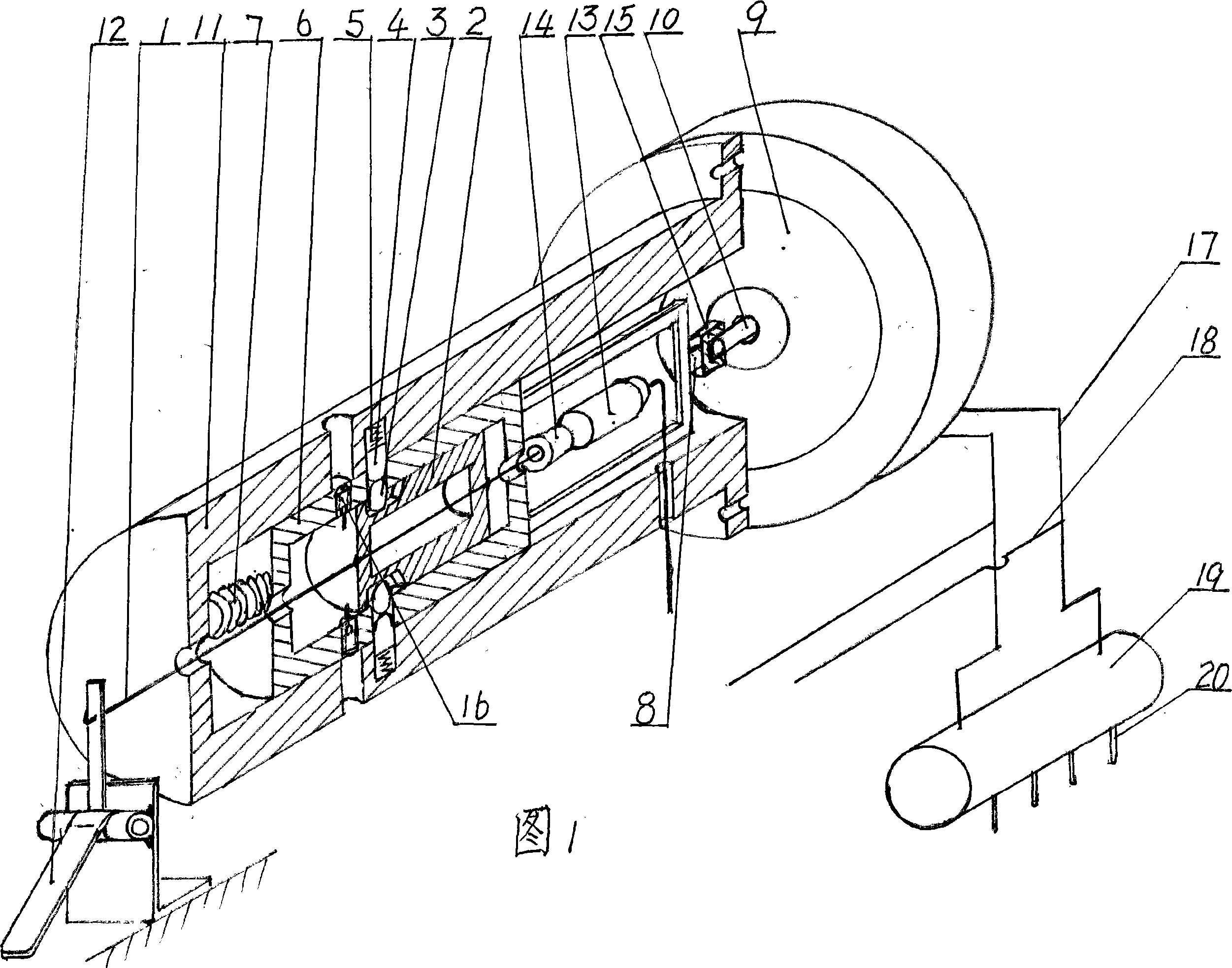
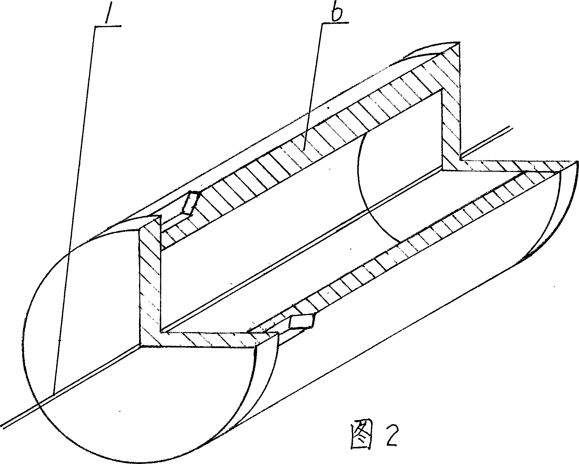
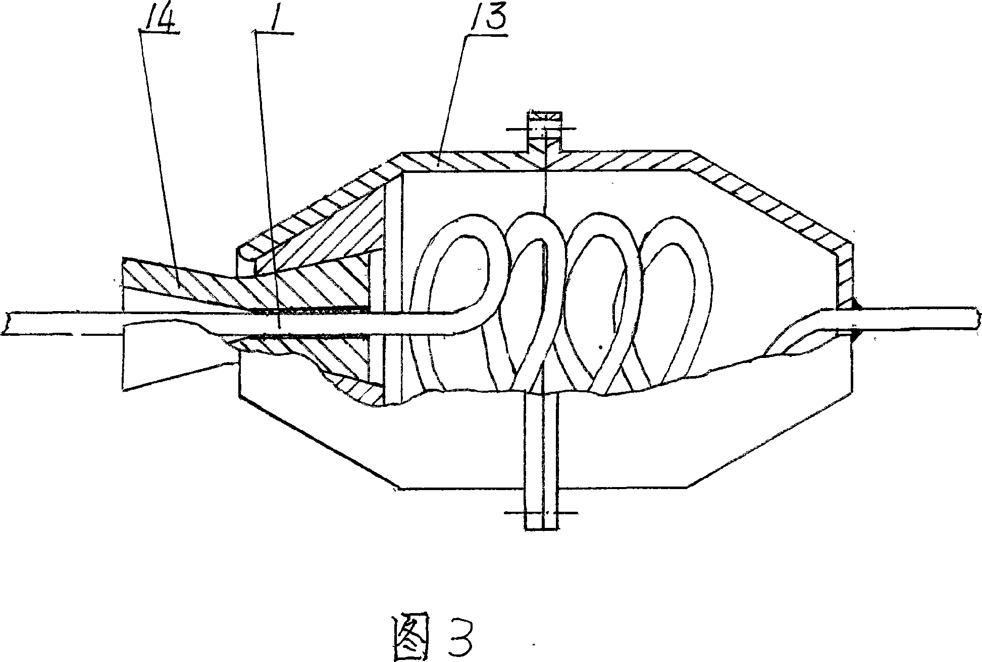
[0016] As shown in Figure 1 and Figure 2: a conversion device is fixed between the accelerator pedal and the booster pump. The conversion device consists of a steel wire rope 1, a slider 2, a pin 3, a pin 4, a small spring 5, a stroke box 6, and a compression spring. 7. Push rod 8, power pump 9, output shaft 10, casing 11, accelerator pedal 12 and looper box 13, one end of steel wire rope 1 is fixedly connected with accelerator pedal 12, and the other end passes through casing 11, stroke box 6 and the slider 2 are welded and fixed on the two ends of the slider 2, the outlet of the slider 2 is fixed with a looper box 13 wound around the steel wire stay rope 1 for three turns, and two valves 14 with trumpet-shaped semicircles at both end...


PUM


Abstract

The invention relates to an automobile throttle over-force switch brake device, the steel wire stay cord on the switching device is immovably connected with gas pedal and slider respectively, the fixed steel wire stay cord on another end of slider is connected with original throttle control, and there are four grooves with slope on the slider, and is inserted with pellets, and circular slot holes are provided on corresponding shell and stroke box for inlaying the pellets, and a little spring is provided on the bottom, and the stroke box is blocked by two pellets, and the pressure spring is placed between the stroke box and the shell, and stroke box tip has frame and ejector pin, and it is pushed on the shaft. When accident happens, step on the gas footboard with strength and pulls the steel wire stay cord and slider, and driving the stroke box to compress the pressure spring tightly, pop out the stroke box with certain distance under the effect of pressure spring and the little spring, the plug promotes out the shaft forward, and the oil pipe on the helping pump dispenses oil to four wheels through the oil dispenser to realize braking of the car. Advantages are: the structure is simple, and the action is sensitive accurate, and is safe and reliable, which is easy for operation, and the dismounting is convenient.

Description

technical field [0001] The invention belongs to automobile parts, in particular to an automobile throttle overforce conversion braking device Background technique [0002] As we all know, at present, the accelerator and brake of the car are operated by the driver's right foot, and the pedals of the accelerator and brake are next to each other. Moreover, the accelerator pedal is lower than the brake pedal. When there is an emergency, the driver is easy to mistake the accelerator pedal for The brake pedal, after stepping hard to refuel, causes the car to rush forward and cause an accident. Sometimes, the driver does not lift the foot but only moves a distance, which is regarded as the brake pedal. In fact, the foot is under the brake pedal, and the inner side of the foot is still connected to the accelerator pedal. Contact, step hard or step on the accelerator pedal, the car rushes forward and causes an accident, especially for students who are just learning to drive, the abov...

Claims


Application Information

Patent Timeline
Patent Type & Authority Applications(China)
IPC IPC(8): B60K26/02B60T7/06B60W10/06B60W10/18B60W30/08B60W10/184B60W30/09
Inventor 邓瑞祥
Owner 邓瑞祥
Why Eureka
Try Eureka