Heat pipe

A heat pipe and heat transfer technology applied to heat pipes. It can solve the problems of unfavorable heat transfer of heat pipes, hinder the return of condensed liquid, and slow down the response time of heat pipes to temperature, so as to achieve the effect of enhancing heat transfer capacity

Inactive Publication Date: 2007-10-17
FU ZHUN PRECISION IND SHENZHEN +1
View PDF0 Cites 10 Cited by
  • Summary
  • Abstract
  • Description
  • Claims
  • Application Information

AI Technical Summary

Problems solved by technology

[0005] The existing heat pipe is limited by the small heat absorption area of ​​the evaporating section, so that the heat from the heat source is not easily absorbed by the evaporating section to cause overheating. Restricted, if the evaporating section cannot maintain close thermal contact with the heat source and the condensing section and the cooling device, the situation will be more serious, which will hinder the reflux of the condensed liquid through capillary force, and then dry up early and heat up rapidly, limiting its The maximum heat transfer; and due to the high length / diameter ratio of the heat pipe, the heat is lost during the heat transfer process through the steam, so that part of the steam flowing through the center of the heat pipe is condensed into liquid droplets in advance and mixed in the steam flow, so that The speed of steam absorbed and evaporated by the evaporating section to the condensing section along the steam flow channel is reduced or even blocked to limit the heat transfer of the steam, which increases the thermal resistance of the heat pipe and causes the temperature difference between the evaporating section and the condensing section to increase, and Reduce the maximum heat transfer capacity of heat pipes, which is especially unfavorable for long-distance heat transfer using heat pipes
[0006] The method of existing heat pipe technology to increase the maximum heat transfer is to increase the thickness of the capillary structure layer of the entire heat pipe to increase the water content in it, but relatively, it also slows down the response time of the heat pipe to temperature and increases the temperature difference; Conversely, the way to reduce the temperature difference is to thin the thickness of the capillary structure layer of the whole heat pipe to reduce the water content in it, but relatively, it also reduces the maximum heat transfer of the heat pipe. It can be seen that the existing heat pipe technology cannot take care of improving the maximum heat transfer. heat and reduce the temperature difference, thus forming a contradiction that is more difficult to overcome

Method used


Image

  • Heat pipe
  • Heat pipe
  • Heat pipe

Examples


Embodiment Construction

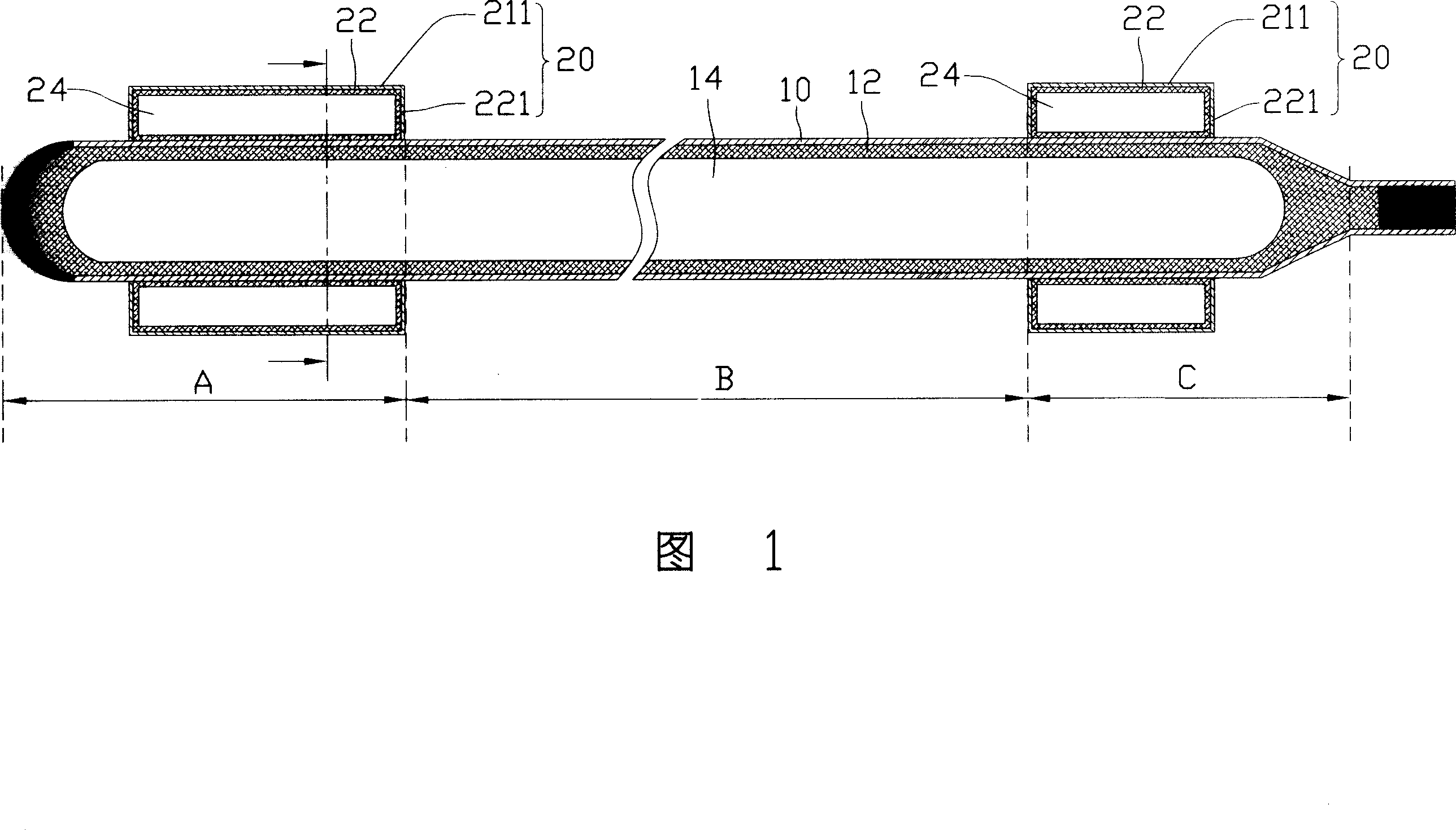
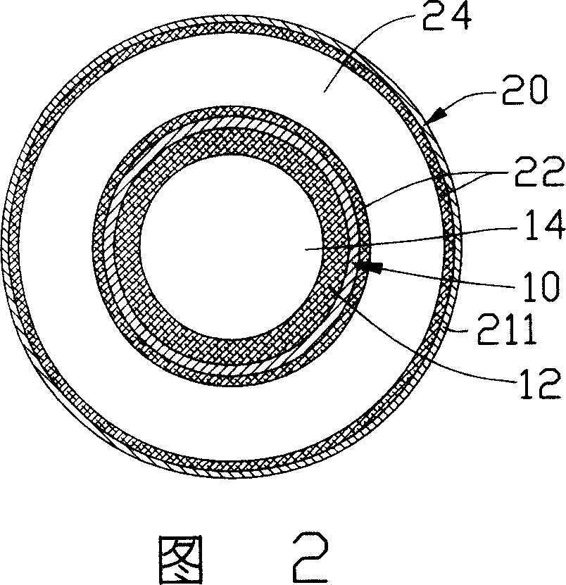
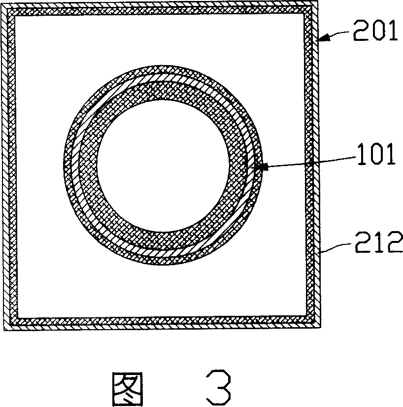
[0016] Please refer to FIG. 1, which is a longitudinal cross-sectional view of the first embodiment of the heat pipe of the present invention; the heat pipe shown includes a sealed heat transfer cavity 10, the inner wall of which is provided with a capillary structure 12 for reflux of condensate, and the capillary structure 12 The space in the center of the inner side is the steam channel 14, and the heat transfer cavity 10 is enclosed with a proper amount of working fluid and can be properly pumped to a certain degree of vacuum; the heat transfer cavity 10 along the length of the cavity is based on the function of each section It can be divided into a condensing section A, an evaporation section C and an adiabatic section B located between the two; the outer walls of the corresponding condensation section A and the evaporation section C of the heat transfer cavity 10 are respectively sealed with a heat storage cavity 20. Wherein, the heat transfer cavity 10 and the heat storage c...


PUM


Abstract

The invention discloses a heat pipe which includes a sealed heat transmission cavity whose inner wall is equipped with capillary structure and in which appropriate working liquid is sealed. The heat transmission cavity can be divided into evaporation section, condensation section, thermal insulation section between the former two sections along the cavity length direction. The heat pipe also includes two sealed heat accumulation cavities which are respectively arranged on the outer wall of evaporation section and condensation section corresponding to the heat transmission cavity. The heat pipe promotes maximum radiation capacity for the heat pipe and reduces temperature difference between the evaporation section and the condensation section by larger heat absorption area and radiation area and latent heat of external part of the heat accumulation cavity.

Description

【Technical Field】 [0001] The invention relates to a heat conduction device, in particular to a heat pipe. 【Background technique】 [0002] The heat pipe has the characteristics of ultra-quiet, fast heat transfer, high thermal conductivity, light weight, small size, no moving parts, simple structure and multi-purpose, and the heat pipe can quickly transfer a large amount of heat energy under the condition of almost constant temperature. The role of superconductor is widely used; its basic structure is to line the inner wall of a closed pipe with a capillary structure layer that easily absorbs the actuating fluid, and the central space is hollow, and the evacuated closed pipe is filled with equivalent capillary The working fluid of the total pore volume of the structural layer can be divided into the evaporation section, the condensation section and the adiabatic section in between according to the relative position of absorbing and dissipating heat; its working principle is through...

Claims


Application Information

Patent Timeline
Patent Type & Authority Applications(China)
IPC IPC(8): F28D15/04
CPCF28D15/0275F28D15/04
Inventor 刘泰健童兆年侯春树孙至贤
Owner FU ZHUN PRECISION IND SHENZHEN
Why Eureka
Try Eureka