
Logic part and magnetic logic part array based on the dual potential base magnetic tunnel junction

A magnetic tunnel junction and logic element technology, applied in the field of magnetic logic, can solve the problems of unfavorable miniaturization and integration of magnetic logic

Active Publication Date: 2007-10-17
INST OF PHYSICS - CHINESE ACAD OF SCI
View PDF0 Cites 12 Cited by
  • Summary
  • Abstract
  • Description
  • Claims
  • Application Information

AI Technical Summary

Problems solved by technology

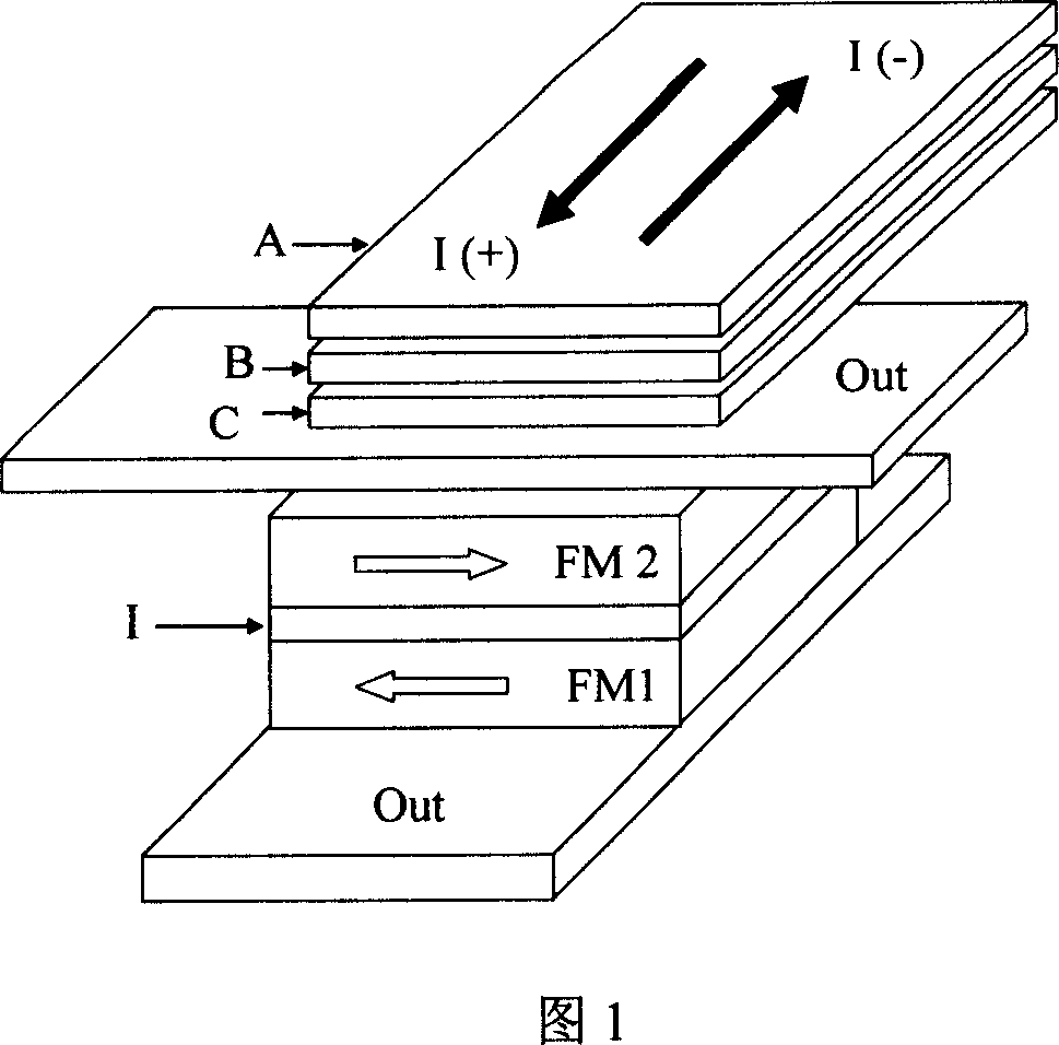
[0005] The purpose of the present invention is to overcome the defect that existing magnetic logic is unfavorable for miniaturization and integration, thereby providing a kind of small-scale logic element based on double-barrier magnetic tunnel junction with multiple logic functions and capable of logic processing

Method used


Image

  • Logic part and magnetic logic part array based on the dual potential base magnetic tunnel junction
  • Logic part and magnetic logic part array based on the dual potential base magnetic tunnel junction
  • Logic part and magnetic logic part array based on the dual potential base magnetic tunnel junction

Examples


Embodiment 1

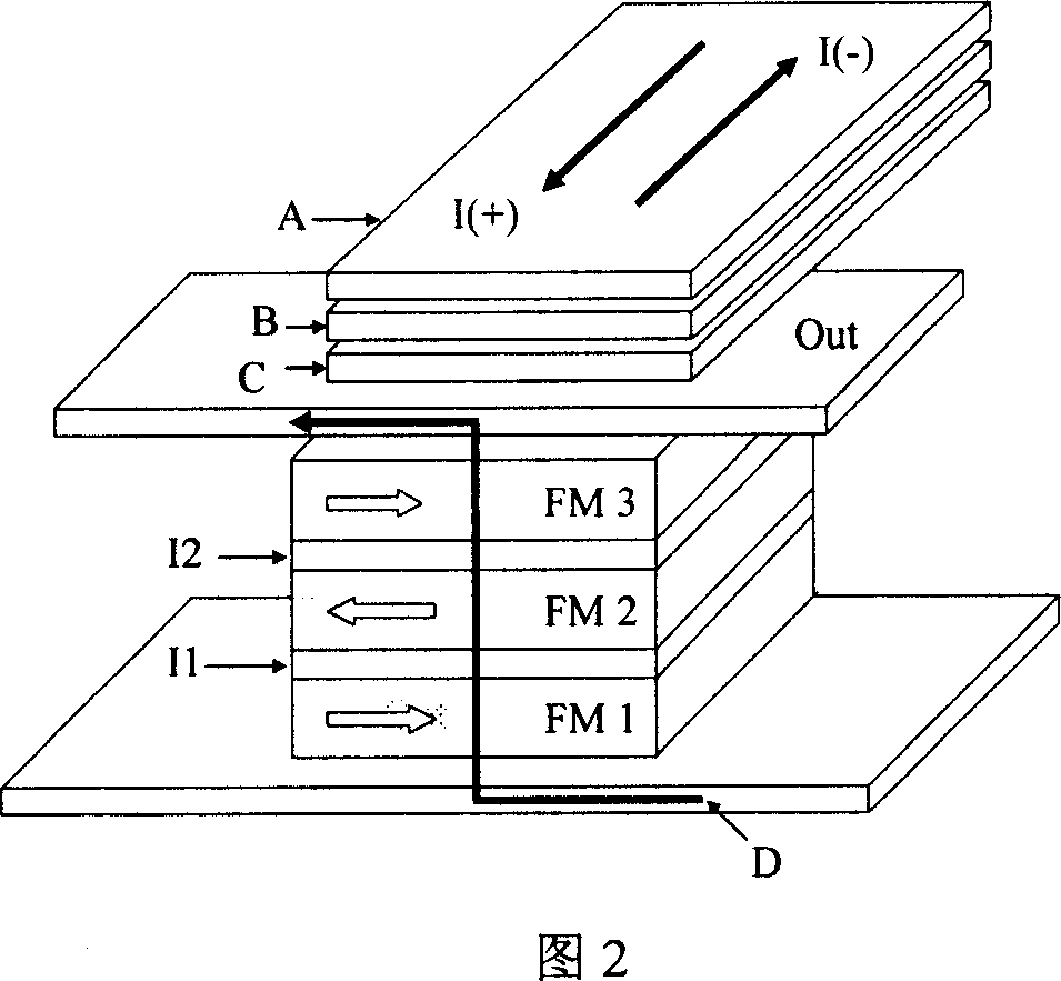
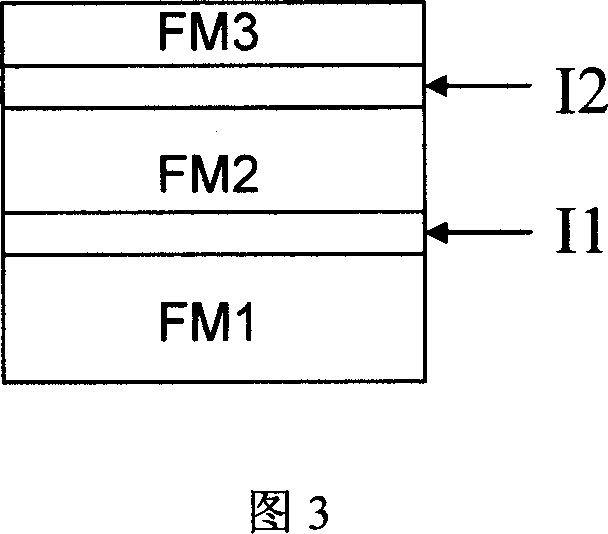
[0041] As shown in Figure 3, the first magnetic logic element core structure based on the double-barrier magnetic tunnel junction provided by the present invention includes the following five layers: three ferromagnetic layers FM1, FM2 and FM3, and in the middle of the three ferromagnetic layers Sandwich two tunnel barrier layers I1 and I2. The magnetic layers FM1 and FM3 are composed of "hard magnetic layer" CoFe with a large coercive force, and its thickness is 3nm. The magnetic layer FM2 is composed of a "soft magnetic layer" NiFe with a small coercive force of 10nm; the tunnel barrier layer is composed of 1.0nm Al 2 o 3 constitute.

[0042] Since the material composition and thickness of the magnetic layers FM1 and FM3 are the same, the switching fields of the two layers are the same, and the magnetization state of the double-barrier tunnel junction at this time is similar to that of the single-barrier tunnel junction. In this scheme, the input lines A, B, and C are arran...

Embodiment 2

[0050] As shown in Figure 4, the second magnetic logic element core structure based on the double barrier magnetic tunnel junction provided by the present invention includes the following five layers: three layers of ferromagnetic layers FM1, FM2 and FM3, and in the middle of the three layers of ferromagnetic layers Sandwich two tunnel barrier layers I1 and I2. The magnetic layers FM1, FM2 and FM3 are made of 4nm CoFeSiB soft magnetic material with high spin polarizability. Among them, FM1 and FM3 are pinned by 12nm antiferromagnetic material IrMn, so that the magnetization direction of the two layers is relatively fixed, while the magnetization direction of FM2 can be reversed in a small magnetic field, which is the free layer. Tunnel barriers I1 and I2 are made of AlN with a thickness of 0.8nm.

[0051] The operation mode of the magnetic logic element based on this structure is similar to Embodiment 1.

Embodiment 3

[0053] As shown in Figure 5, the core structure of the third magnetic logic element based on the double barrier magnetic tunnel junction provided by the present invention includes: a lower antiferromagnetic layer AFM1; an artificial antiferromagnetic coupling structure composed of FM11 / Ru / FM1 The lower magnetic layer; an upper magnetic layer composed of FM3 / Ru / FM31 artificial antiferromagnetic coupling structure; and two tunnel barrier layers I1 and I2 sandwiched between the three ferromagnetic layers (FM1, FM2, FM3); a Upper antiferromagnetic layer AFM2. FM1, FM2 and FM3 are composed of 4nm CoFeB soft magnetic material with high spin polarizability, FM11 and FM31 are composed of 2nm CoFe material, and the thickness of Ru is 0.8nm. Among them, FM1 and FM3 are artificially antiferromagnetically pinned by antiferromagnetic materials PtMn and CoFe(2nm) / Ru(0.8nm) / CoFeB(4nm), the magnetization direction of these two layers is relatively fixed, while the magnetization direction of F...


PUM


Abstract

The invention relates to a logical element based on double potential barrier magnetic tunnel junction, which comprises four input signal lines, an output signal line and a tunnel junction unit; the current intensity passing through each input line are all the same, repectively allocating '0' and '1' to them, and using the combination of input signals A, B, C, D, to decide the magnetization direction of magnetosphere in the tunnel junction, and then taking the size of the magnetoresistance effect through the double potential barrier magnetic tunnel junction as the output signal; it is characterized in that the described tunnel junction unit is double potential barrier magnetic tunnel junction unit, which comprises: a bottom magnetosphere, a first tunnel barrier layer, an intermediate magnetosphere, a second tunnel barrier layer and a top magnetosphere. The invention also relates to a magnetic logical element array that arranges the above-mentioned arbitrary a plurality of magnetic logical elements according to the array, and makes logic input signala or read current flow through the magnetic logical element. The advantage of the invention lies in the miniaturization of the logic circuit and a high density integration, which is helpful for industrialization.

Description

technical field [0001] The invention belongs to the field of magnetic logic, and in particular relates to a digital storage technology utilizing magnetic random access storage, a logic element based on a double-barrier magnetic tunnel junction provided for a logic device and a logic circuit, and an arrayed magnetic array of logic elements. Background technique [0002] Current transistor-based integrated circuits, computing operations, rely primarily on the charge of electrons. However, since the discovery of the giant magnetoresistance effect in the 1980s, spintronics has attracted widespread attention. People want to manipulate the spin of electrons to design and manufacture new devices. Several research groups have begun exploring a whole new class of processors, proposing that magnetic memory cells could also be designed to perform computations. Through the two steps of selection and execution of logical operations, these devices can be either programmable logic device...

Claims


Application Information

Patent Timeline
Patent Type & Authority Applications(China)
IPC IPC(8): H01L43/08G11C11/16H03K19/18H10N50/10
Inventor 曾中明魏红祥姜丽仙韩秀峰彭子龙詹文山
Owner INST OF PHYSICS - CHINESE ACAD OF SCI
Learn More