Vacuum cleaner

A technology for vacuum cleaners and dust collection rooms, which is applied to vacuum cleaners, cleaning equipment, household appliances, etc. It can solve the problems of reducing sound wave energy, vacuum cleaner power loss, and high fan noise, so as to increase gas flow, ensure power, and reduce noise. effect of effect

Inactive Publication Date: 2007-10-24
金日清洁设备(苏州)有限公司
View PDF1 Cites 20 Cited by
  • Summary
  • Abstract
  • Description
  • Claims
  • Application Information

AI Technical Summary

Problems solved by technology

[0002] Vacuum cleaners in the prior art usually include a housing, a fan inside the housing, and a cover outside the fan. Because the noise of the fan is very loud when it is working, especially the noise of high-power vacuum cleaners used in hotels or office buildings It is very large and affects people's normal life and work. In order to alleviate the noise, some sound-absorbing materials, such as sponges, are usually placed on the fan or in the casing.
Chinese patent ZL96207867.0 discloses a low-noise vacuum cleaner, which uses a labyrinth-shaped airflow channel formed by a sound-absorbing cover with a spiral-shaped sound-absorbing channel to extend the travel route of the airflow in the vacuum cleaner, so that the sound waves can pass through the sound-absorbing cover multiple times. Reflection attenuation, thereby reducing the energy of the sound wave. However, in this spiral sound-absorbing structure, the sound wave must go through a long route to attenuate most of the energy; in addition, the spiral sound-absorbing structure severely limits the size of the air volume. The vacuum cleaner will lose some power

Method used


Image

  • Vacuum cleaner
  • Vacuum cleaner

Examples


Embodiment Construction

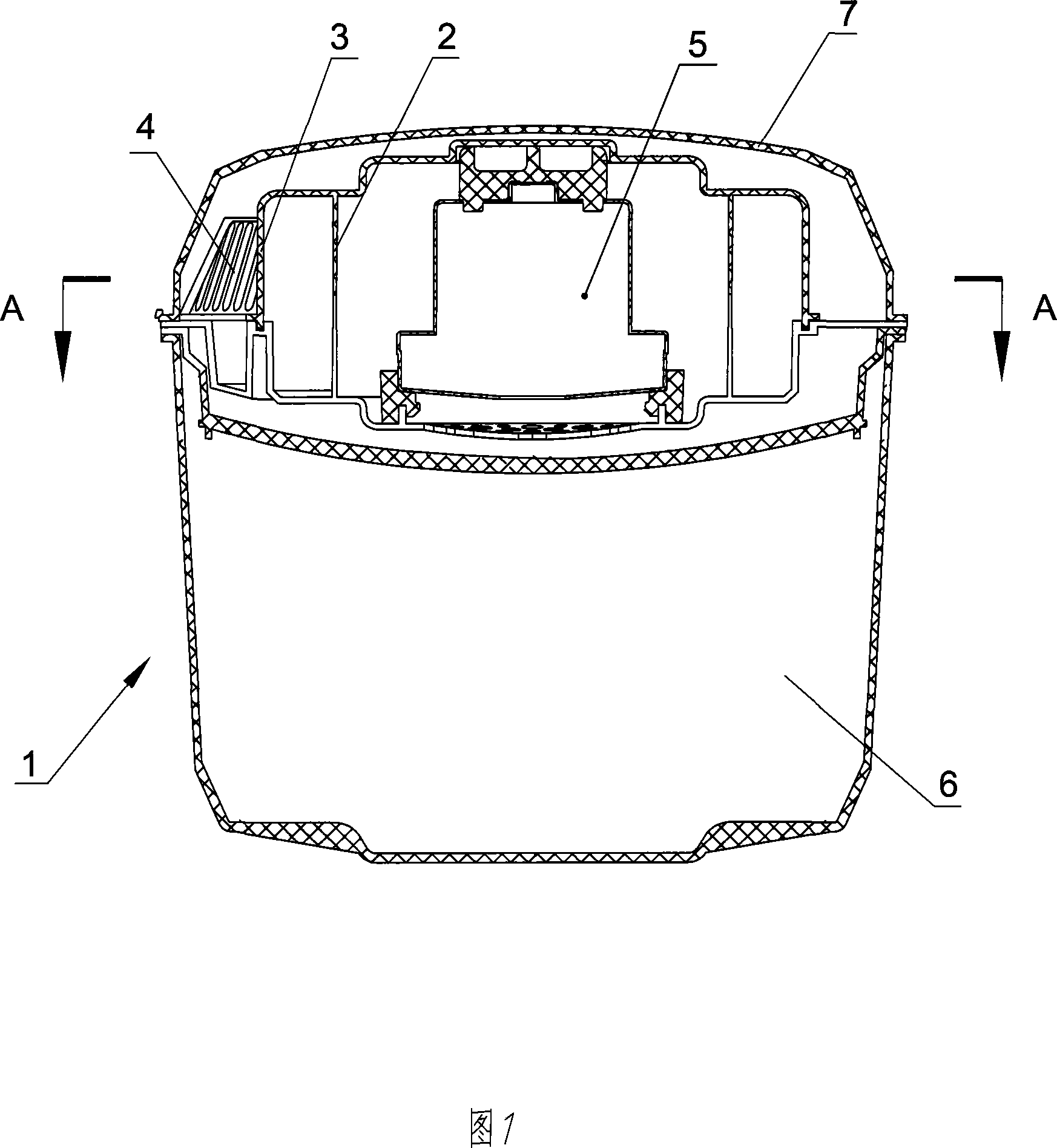
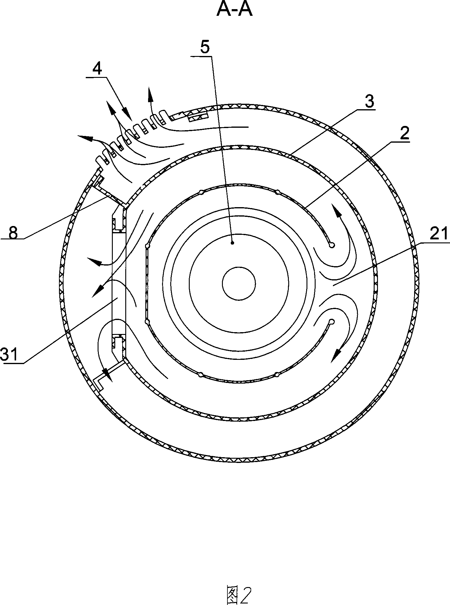
[0014] Accompanying drawing 1~2 is the preferred embodiment of the present invention, a kind of vacuum cleaner, comprises the base 1 that has dust collecting room 6, the blower fan 5 that is arranged on the base 1, the top cover 7 that covers on the base 1, top The cover 7 is provided with an air outlet 4, and the base 1 and the top cover 7 are surrounded by the air outlet 4 to form a cavity that allows the air outlet of the fan 5 to communicate with the outside air. There are also two retaining walls surrounding the fan 5, the retaining walls include the inner retaining wall 2 surrounding the fan 5 and the intermediate retaining wall 3 surrounding the inner retaining wall 3, an intermediate retaining wall 3 is used in this embodiment The baffle, sometimes in order to achieve a better sound attenuation effect, the number of intermediate baffles will be appropriately increased.

[0015] The inner retaining wall 2 and the middle retaining wall 3 extend from the base 1 to the top...


PUM


Abstract

The invention relates to a dust collector, comprising base, fan installed on base and top cover on the base. The base and top cover form a cavity for placing fan, the cavity is connected to air through ventilating port on the top cover, at least two baffle walls around fan are installed between base and top cover, the baffle wall extends to top cover from base, and divides the cavity into a plurality of separate noise reduction room, the baffle wall is also equipped with break and breaks on the near baffle walls are staggering, and the noise reduction rooms are connected to each other through break. The invention reflects sound wave emit from fan to reduce sound energy, so the noise reduction effect is excellent.

Description

technical field [0001] The invention relates to a vacuum cleaner. Background technique [0002] Vacuum cleaners in the prior art usually include a housing, a fan inside the housing, and a cover outside the fan. Because the noise of the fan is very loud when it is working, especially the noise of high-power vacuum cleaners used in hotels or office buildings It is very large and affects people's normal life and work. In order to alleviate the noise, some sound-absorbing materials, such as sponges, are usually placed on the fan or in the casing. However, placing the sponge makes it difficult to dissipate the heat of the fan, causing accidents such as fire. Chinese patent ZL96207867.0 discloses a low-noise vacuum cleaner, which uses a labyrinth-shaped airflow channel formed by a sound-absorbing cover with a spiral-shaped sound-absorbing channel to extend the travel route of the airflow in the vacuum cleaner, so that the sound waves can pass through the so...

Claims


Application Information

Patent Timeline
Patent Type & Authority Applications(China)
IPC IPC(8): A47L5/12A47L9/00
Inventor 卞庄
Owner 金日清洁设备(苏州)有限公司
Why Eureka
Try Eureka