
Hydraulic circuit for traveling priority

A hydraulic circuit and linear movement technology, which is applied in the direction of motor vehicles, earth movers/excavators, fluid pressure actuators, etc., can solve the problems of reducing the operability of mobile devices and reducing work efficiency

Inactive Publication Date: 2007-10-24
SAMSUNG HEAVY IND CO LTD
View PDF2 Cites 21 Cited by
  • Summary
  • Abstract
  • Description
  • Claims
  • Application Information

AI Technical Summary

Problems solved by technology

Therefore, the left shifting pressure and the right shifting pressure are unbalanced, causing the device to tilt to the left or right or to move suddenly, thereby reducing the operability of the shifting device
[0024] Also, if the pressure on the moving side is high and the pressure on the working side is low, hydraulic fluid moves to the work equipment, reducing work efficiency

Method used


Image

  • Hydraulic circuit for traveling priority
  • Hydraulic circuit for traveling priority
  • Hydraulic circuit for traveling priority

Examples


Embodiment Construction

[0038] Hereinafter, preferred embodiments of the present invention will be described with reference to the accompanying drawings. Matters defined in the description, such as detailed structure and elements, are nothing but specific details provided to help one of ordinary skill in the art to fully understand the present invention, and thus the present invention is not limited to these specific details.

[0039] The linear movement hydraulic circuit according to the present invention will now be described in detail with reference to preferred embodiments.

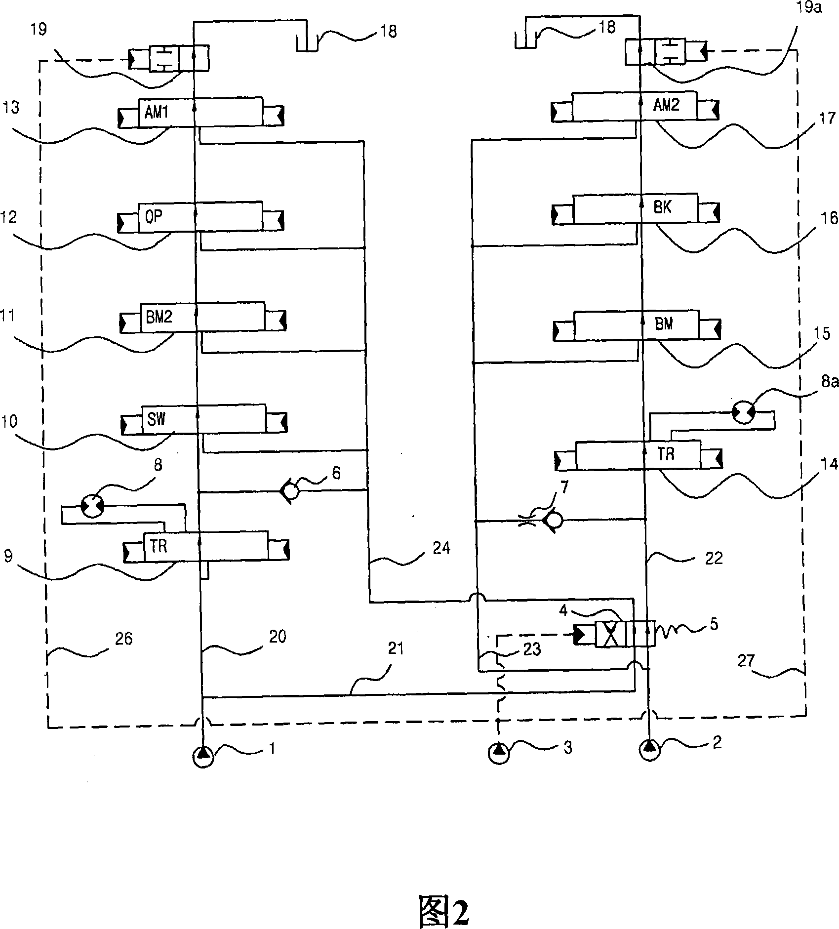
[0040] Referring to Fig. 2, the hydraulic circuit for linear movement according to an embodiment of the present invention includes: a first hydraulic pump 1 and a second hydraulic pump 2; Valve 9 and control valves 10 to 13 for working devices (swing arm, boom, selection device, and robot arm); a first center bypass switching valve 19 installed on the most downstream side of the first center bypass pipe 20 , and when the si...


PUM


Abstract

A straight traveling hydraulic circuit is provided. In case of performing a combined operation in which a fine operation of a working device and a fine traveling of a traveling device are simultaneously required, the straight traveling hydraulic circuit can allow the working device and the traveling device to operate independently, and thus prevent a declination or sudden traveling of the equipment. In case of performing the combined operation by simultaneously operating the traveling device and the working device, first and second center bypass shifting valves installed on the lowermost stream side of first and second center bypass passages are shifted by a pilot signal pressure that shifts a straight traveling valve installed on an upper stream side of the second center bypass passage, so that the degree of opening of the first and second center bypass passages is reduced to operate the working device and the traveling device independently.

Description

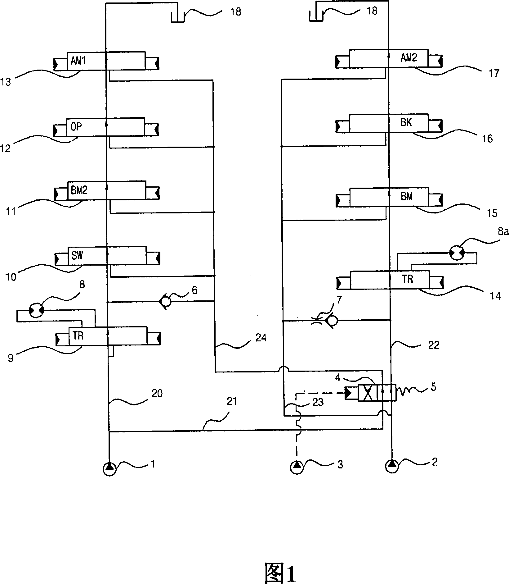
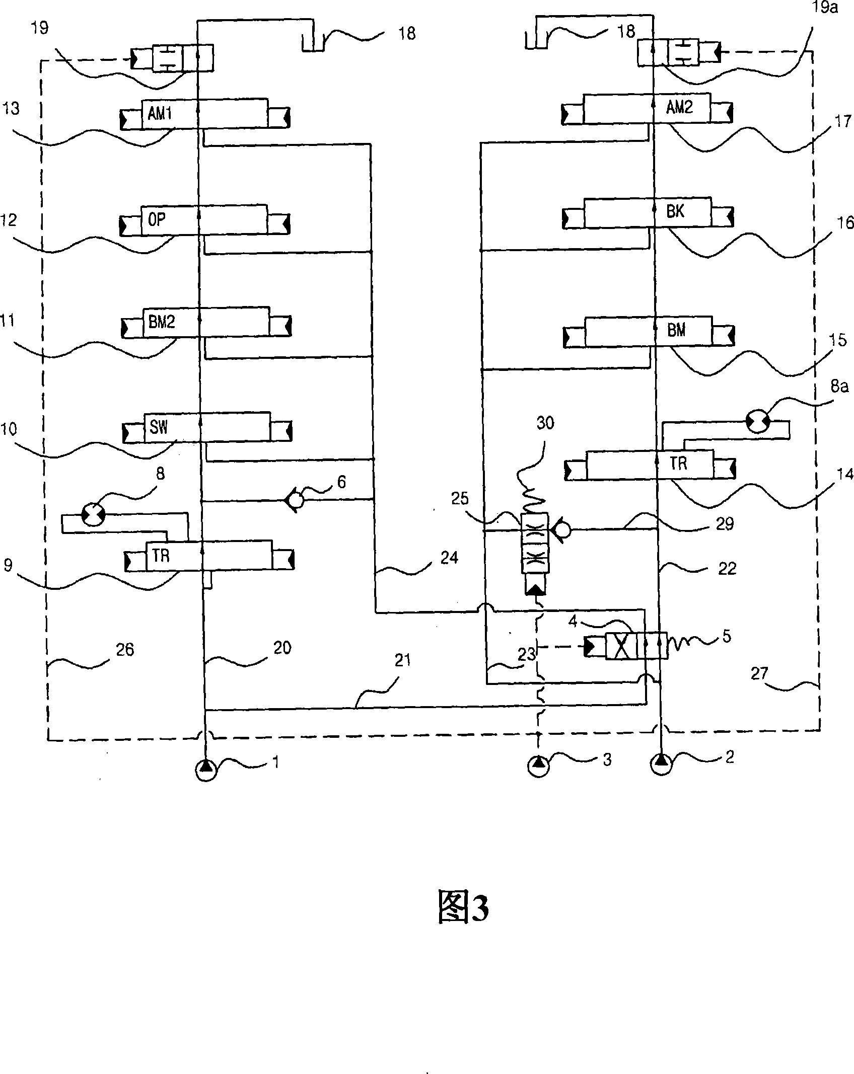
[0001] Cross References to Related Applications [0002] This application is based on and claims the benefit of priority from Korean Patent Applications No. 10-2006-34747 and No. 10-2006-34748 filed with the Korean Intellectual Property Office on April 18, 2006, the disclosure of which is hereby incorporated in its entirety Incorporated by reference. technical field [0003] The present invention relates to a linear moving hydraulic circuit for heavy construction equipment using a plurality of hydraulic pumps, which can improve the maneuverability of the movement of the equipment during a combined operation of simultaneously performing a moving operation and a working operation. [0004] More particularly, the present invention relates to a linear movement hydraulic circuit that can allow heavy construction equipment to move independently of work equipment in the case of combined operations, thereby preventing tilting or sudden movement of the equipment, during combined operat...

Claims


Application Information

Patent Timeline
IPC IPC(8): F15B11/00F15B11/16E02F9/22
CPCB60Y2200/412E02F9/225E02F9/2253E02F9/2264E02F9/2292
Inventor 金镇昱
Owner SAMSUNG HEAVY IND CO LTD
Learn More