Valve core

A technology of the main body and sealing components, which is applied in the direction of lifting valves, valve details, control valves, etc. It can solve the problems of gas leakage, metal components meshing with each other, and metal sealing parts not functioning, so as to achieve high elastic deformation rate and improve tightness Degree, the effect of reducing the amount of leakage

Active Publication Date: 2007-10-24
PACIFIC INDUSTRIAL CO LTD
View PDF0 Cites 6 Cited by
  • Summary
  • Abstract
  • Description
  • Claims
  • Application Information

AI Technical Summary

Problems solved by technology

[0003] However, for example, when the valve body is used in a part receiving high-pressure air pressure such as the flow path of an air conditioner, although the amount is extremely small, the gas may permeate the rubber sealing member and flow to the outside in the closed state of the valve body. leakage
In contrast, a structure including both a rubber seal member and a metal seal is considered, but the metal members constituting the metal seal cannot be meshed with each other only under the action of air pressure and the spring force of the valve core. Ingress, the metal seal may not function
Therefore, gas leakage cannot be reliably reduced

Method used


Image

  • Valve core
  • Valve core
  • Valve core

Examples


no. 1 approach

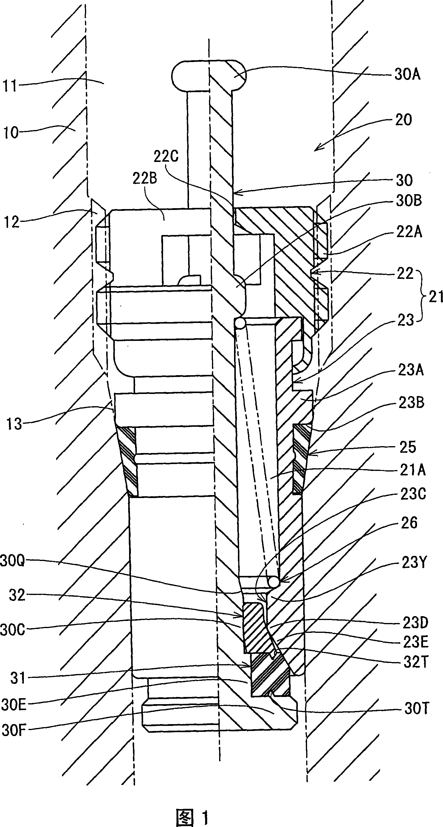
[0020] Hereinafter, a first embodiment of the present invention will be described based on FIGS. 1 to 4 . Reference numeral 10 in FIG. 1 is a valve main body corresponding to the "core holding member" of the present invention, which is, for example, in the shape of a nozzle and has a core fitting hole 11 in the axial center. In addition, a female thread portion 12 is provided in the middle of the core fitting hole 11, and a tapered portion 13 whose inner diameter gradually decreases is provided on the inner side (lower side in FIG. 1 ) of the female thread portion 12 .

[0021] In addition, the "core holding member" of the present invention is not limited to a nozzle shape as described for the valve main body 10, and may be, for example, a wall member constituting a container case as long as it has a core fitting hole 11.

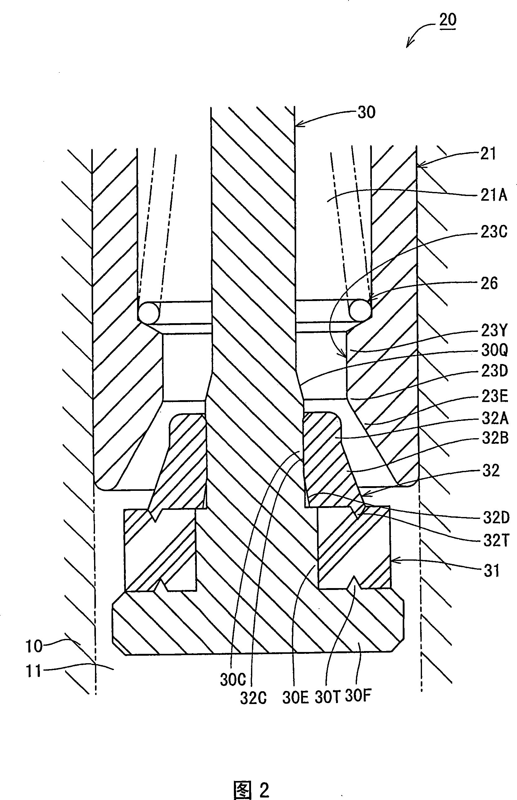
[0022] The valve core 20 of the present invention includes a cylindrical core body 21 , and the movable shaft 30 is inserted through an insertion hole 21A ...

no. 2 approach

[0040] As shown in FIG. 5 , the valve core 20 of this embodiment differs from the first embodiment only in the structure of the contact portion between the metallic glass sealing member 32 and the core main body 21 . Hereinafter, the same reference numerals as those in the first embodiment are assigned to the same configurations as those of the first embodiment, overlapping descriptions will be omitted, and only configurations different from those of the first embodiment will be described.

[0041] The sealing member 33 made of metallic glass according to the present embodiment has a first flat surface 33A facing the base end side of the movable shaft 30 at an intermediate portion in the axial direction, and an annular protrusion 33B protrudes from the first flat surface 33A. In addition, the first flat surface 33A and the annular protrusion 33B are continuously formed over the entire circumference of the sealing member 32 made of metallic glass.

[0042] On the other hand, on...

no. 3 approach

[0045] In this embodiment, as shown in FIG. 6 , instead of the annular protrusion 33B included in the metallic glass sealing member 33 of the second embodiment, an annular protrusion is formed protruding from the second flat surface 23F of the core body 21 . 23G structure. This configuration also provides the same operational effects as those of the second embodiment.


PUM


Abstract

A valve core includes a cylindrical core base fixed in a mounting hole having an inner circumferential surface, a movable shaft extending through the core base so as to be movable, the movable shaft having a distal end, a first sealing member made from rubber and located on the distal end of the movable shaft so as to adhere closely to a distal end of the core base or the inner circumferential surface of the core mounting hole, thereby closing the core mounting hole, and a second sealing member made of a metal glass and located on the distal end of either one of the movable shaft and the core base so as to adhere to the distal end of the other, thereby closing the core mounting hole.

Description

technical field [0001] The present invention relates to a valve core which is installed in a core mounting hole of a core holding member and closes the core mounting hole. Background technique [0002] Conventionally, as this type of valve element, a valve element is known in which a rubber seal member is provided at the front end of a movable shaft passing through a cylindrical core body, and the rubber seal member is in close contact with the front end of the core body. , Closed core assembly holes (for example, refer to paragraphs [0034] to [0036], Fig. 6 of JP 2004-68954 Bulletin). [0003] However, for example, when the valve body is used in a part receiving high-pressure air pressure such as the flow path of an air conditioner, although the amount is extremely small, the gas may permeate the rubber sealing member and flow to the outside in the closed state of the valve body. leakage. In contrast, a structure including both a rubber seal member and a metal seal is con...

Claims


Application Information

Patent Timeline
Patent Type & Authority Applications(China)
IPC IPC(8): F16K1/36F16K1/46
CPCB60C29/002B60C29/00F16K25/005Y10T137/3786F16K15/20F16K1/36
Inventor 山本雅彦
Owner PACIFIC INDUSTRIAL CO LTD
Why Eureka
Try Eureka