Diagnostic signal processor

A signal processing device and processing device technology, applied in the direction of switchgear, measuring device, switchgear setting, etc., can solve the problems of limited delivery time, large application, and no unit ready to collect new information, etc., and achieve low cost Effect

Inactive Publication Date: 2010-11-17
MITSUBISHI ELECTRIC CORP
View PDF6 Cites 0 Cited by
  • Summary
  • Abstract
  • Description
  • Claims
  • Application Information

AI Technical Summary

Problems solved by technology

However, since the rules for final discharge estimation are fixed and the same processing is applied to all sensors, the processing function as a system is fixed, for example, depending on the noise environment of the site or the operating time of the gas-insulated equipment The change of the part of the discharge source that should be regarded as the key management object, etc., when the predetermined signal processing rules cannot fully meet the requirements of information processing, the system must be completely rebuilt
In addition, even if further detailed information is collected when the partial discharge detection signal is issued, there is no unit for collecting additional new information, and it is necessary to send a technician to the site, etc., which becomes a big problem in terms of cost and operation.
[0008] In addition, in the above conventional method, when the number of partial discharge sensors is increased by adding gas-insulated equipment, information processing systems having the same information processing algorithm are repeatedly added, and at the same time, data of these additions are included and used as a new system To play a role, it is necessary to create new and change the overall system control software, which brings great constraints in terms of cost and delivery deadline

Method used


Image

  • Diagnostic signal processor
  • Diagnostic signal processor
  • Diagnostic signal processor

Examples


Embodiment Construction

[0041] Embodiment 1

[0042] Below, refer to Figure 1 to Figure 5 A diagnostic signal processing device according to Embodiment 1 of the present invention will be described.

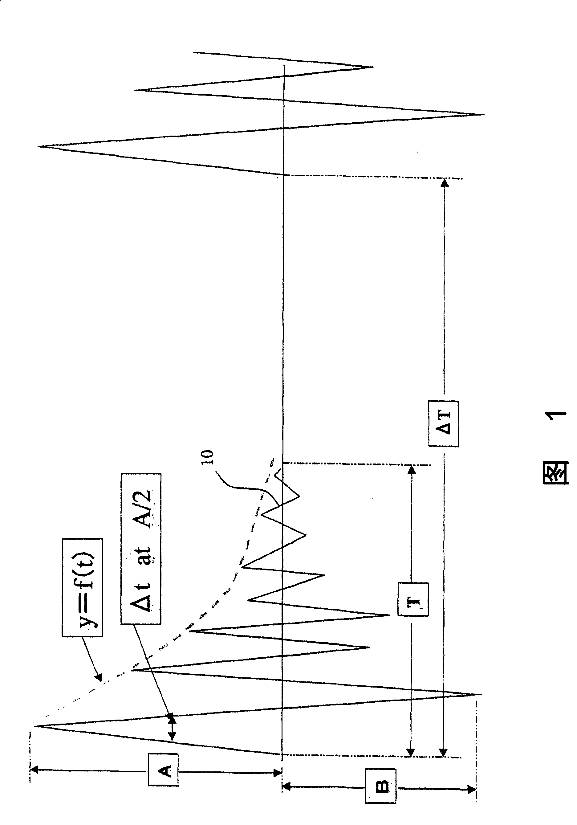
[0043] figure 1 A typical waveform diagram of a partial discharge sensor signal according to Embodiment 1 of the present invention is shown. figure 1 Among them, A is the peak value of the first positive wave of the high-frequency partial discharge signal waveform, B is the peak value of the first negative wave, Δt is the half-value width of the first positive wave peak A, and y represents the function of the envelope waveform of the high-frequency signal, T is the decay time constant of the high-frequency signal, and ΔT is the pulse period between the partial discharge signals, and these are used to represent the characteristics of the partial discharge signal waveform.

[0044] That is, the first positive peak value A of the high-frequency partial discharge signal waveform is the amplitude correspo...


PUM


Abstract

The invention discloses a signal processing device used for diagnosing a piece of gas insulated equipment, which can flexibly deal with various changes of processing conditions when predetermined signal processing rules can not be fully used for dealing with the requirements of information processing. The signal processing device used for diagnosing the gas insulated equipment is provided with a sensor component 2 that decomposes partial electromagnetic wave signals which are transmitted in the detected gas insulated equipment and detected by a discharging sensor 1 into a plurality of characteristic quantities corresponding to various physical quantities expressed by signal waveforms and collects the characteristic quantities. The characteristic quantities collected by the sensor assembly2 are a first positive wave crest value A, a first negative wave crest value B, the half-value width Delta T of the first wave crest value, the envelope waveform y of a high-frequency signal, a decaytime constant T of the high-frequency signal, pulse interval information Delta T of partial discharged signals and pulse density N.

Description

technical field [0001] The present invention relates to a signal processing device for diagnosis used in a diagnosis system for diagnosing partial discharge in gas-insulated equipment. Background technique [0002] Typical methods of partial discharge signal processing related to conventional gas-insulated equipment include, for example, signal processing methods disclosed in JP-A-2001-242212 and JP-A-2001-183411. [0003] Japanese Unexamined Patent Publication No. 2001-242212 discloses a technique of detecting a signal of a partial discharge sensor, converting it into data of half-value width and peak value of the signal, and estimating the discharge source by using the ratio thereof. [0004] In addition, the technology disclosed in Japanese Patent Application Laid-Open No. 2001-183411 is to start the timer at the moment when the partial discharge signal is detected, and store the successive partial discharge signals in time sequence as the function of discharge informatio...

Claims


Application Information

Patent Timeline
Patent Type & Authority Patents(China)
IPC IPC(8): G01R19/04G01R31/12G01R23/00G01R29/02G01R19/00G01R31/00H02B13/065
CPCG01R31/1254
Inventor 龟井光仁西田智惠子
Owner MITSUBISHI ELECTRIC CORP
Why Eureka
Try Eureka