Line focusing metal flow passage solar vacuum heat-collecting tube and fabrication technology thereof

A vacuum heat collector tube and metal flow channel technology, applied in the field of solar thermal utilization, can solve the problems of limited use range, low sealing temperature and high heat loss probability

Inactive Publication Date: 2007-10-31
中金盛唐新能源科技(北京)有限公司
View PDF2 Cites 30 Cited by
  • Summary
  • Abstract
  • Description
  • Claims
  • Application Information

AI Technical Summary

Problems solved by technology

However, in the production and use of the example, it is found that the sealing structure of the heat collecting tube is facing a severe test on the high-magnification focusing device. Since the example uses the domestic mature lead pressure sealing technology, the sealing temperature is lower than the temperature of the working medium in the tube. thus limiting the scope of use of the technology
At the same time, the exposed external unloading device also has the defect of high heat loss probability. In order to expand the applic...

Method used


Image

  • Line focusing metal flow passage solar vacuum heat-collecting tube and fabrication technology thereof
  • Line focusing metal flow passage solar vacuum heat-collecting tube and fabrication technology thereof

Examples


Embodiment 1

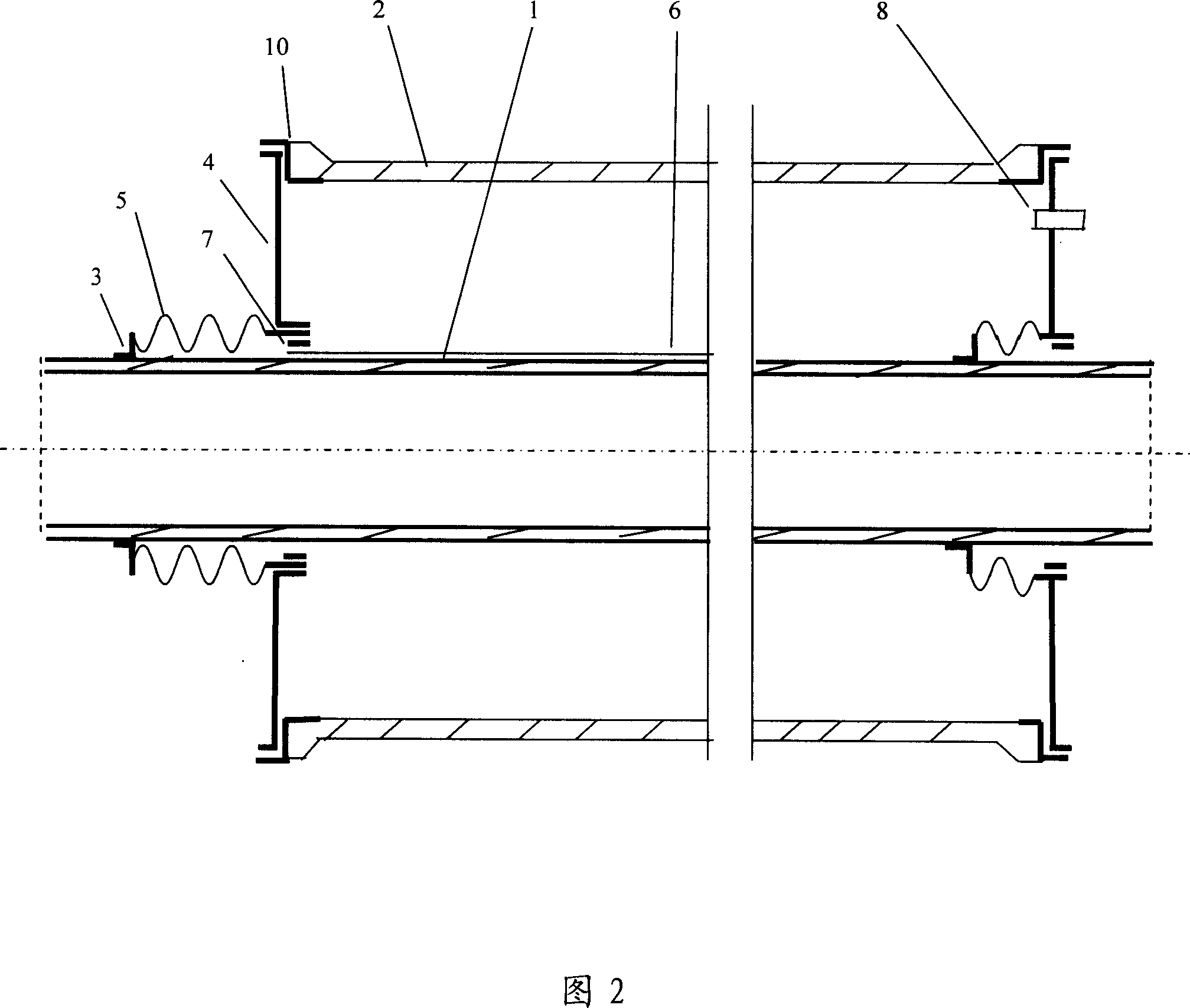
[0031] 1) The iron-nickel alloy kovar process ring and the glass outer tube are welded and sealed into a single component by indirect fusion sealing process, that is, component 1: firstly, the iron-nickel kovar alloy plate is stamped and stretched to make convex rings with different inner circles Its convex top is turned outward by 1-3mm, and the ring surface and elevation are indirectly sealed with the inner wall of the glass tube and the plane of the glass flange to ensure that the depth of the seal and the width of the plane seal are each 10mm. The coefficient of linear expansion is less than 48×10 -7 / °C.

[0032] 2) In order to prevent harmful air bubbles from appearing at the interface between the kovaring part 6 and the glass during sealing, the iron-nickel kovaring part is degassed and decarburized in high temperature and wet hydrogen according to the conventional process, that is, heat treatment by burning hydrogen;

[0033] 3) Atomization is carried out after serv...

Embodiment 2

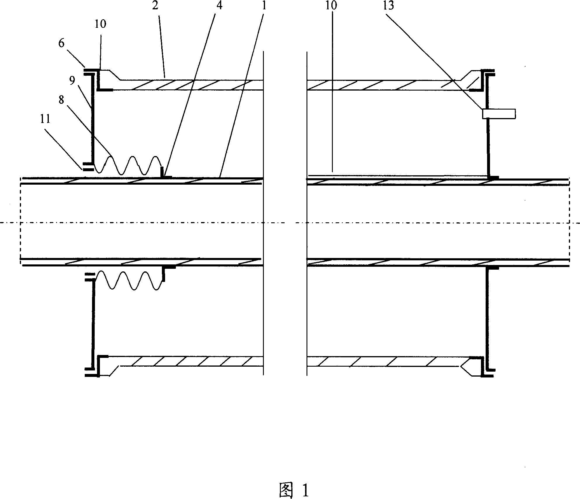
[0045] 1) The bellows 8 of the external unloading device are arranged at both ends. Turn the inner circles of the two metal end caps 9 inwardly and outwardly.

[0046] 2) According to the unloading absorption of the bellows 8, the wave number is divided into two sections, one section is set inside the metal end cap 9 and the glass tube 2, and the other section is set outside the metal end cap 9 and the glass tube 2.

[0047] 3) One end of the bellows 8 of the external unloading device is welded with the inner circle of the metal end cover 9 that is flanging outward and the heat insulation process ring 11 that is close to the inner wall of one end of the bellows 8 to form the external unloading device component 2A .

[0048] 4) One end of the bellows 8 of the built-in external unloading device is welded with the inner circle of the metal end cap 9 flanging inward and the heat insulation process ring 11 close to the inner wall of one end of the bellows 8 to form the external ex...


PUM

PropertyMeasurementUnit
Softening temperatureaaaaaaaaaa
Linear expansion coefficientaaaaaaaaaa

Abstract

The invention relates to line focus metal flow passage solar vacuum heat collecting tube and its manufacturing technique, mainly to solve the problem of the prior art that the large external heat loss and sealing mechanical stability of the sealing terminal of the metal flow passage solar vacuum heat collecting tube. The line focus metal flow passage solar vacuum heat collecting tube comprises a glass outer tube, a metal inner tube, an external unloading device and a tube connecting element. The adjusted indirect sealing connecting method of The invention apparently improves the connecting mechanical intensity of the metal flow passage solar vacuum heat collecting tube, and the stability of the metal flow passage solar vacuum heat collecting tube is improved. The invention could be widely used in the solar medium-high-temperature heat collecting device of the groove style solar heat power generation, solar air conditioner refrigeration, solar sea water desalting and so on.

Description

technical field [0001] The invention relates to a solar vacuum heat collecting tube with a built-in metal flow channel used in a trough-type line focusing and a compound parabola, that is, a CPC concentrating device. Its structure and manufacturing process are suitable for various straight-through solar vacuum heat collecting tubes with a built-in metal flow channel. It belongs to the technical field of solar thermal utilization. Background technique [0002] With the vigorous development of the use of renewable energy such as solar energy in the world, solar thermal power generation, solar refrigeration air conditioning, solar desalination and other solar energy industrial heat utilization technologies are gradually recognized by people, and the establishment of these solar heat utilization devices is inseparable from the trough (Parabolic) line focusing and compound paraboloid are CPC concentrating devices, and line focusing solar collector tube is the main heat collecting...

Claims


Application Information

Patent Timeline
IPC IPC(8): F24J2/46B23P15/26
CPCY02B10/22Y02E10/40Y02A20/142Y02B10/20
Inventor 张建城
Owner 中金盛唐新能源科技(北京)有限公司
Why Eureka
Try Eureka