
Drive circuit and method for florescent lamp

A driving circuit and driving method technology, applied in the field of fluorescent lamps, can solve problems such as the inability to open the load, the saturation of magnetic components, the inability to start accurately and quickly, etc.

Inactive Publication Date: 2007-10-31
DELTA ELECTRONICS INC
View PDF0 Cites 2 Cited by
  • Summary
  • Abstract
  • Description
  • Claims
  • Application Information

AI Technical Summary

Problems solved by technology

It can be seen from the figure that this starting method is a resonance boosting method. In addition to the disadvantages of high starting current, easy to saturate magnetic components, high circulating current, and load cannot be opened, it still takes a while to start using the resonance method. The lighting voltage of the lamp body is raised to the actual required lighting voltage, so it cannot be started accurately and quickly

Method used


Image

  • Drive circuit and method for florescent lamp
  • Drive circuit and method for florescent lamp
  • Drive circuit and method for florescent lamp

Examples


Embodiment Construction

[0021] The present invention discloses a driving circuit and method for a fluorescent lamp. The content will be described as follows with the help of a preferred embodiment. Those skilled in the art can implement the present invention according to the technical content, but this embodiment is only one of the preferred ones. , the implementation of the present invention is not limited to this embodiment.

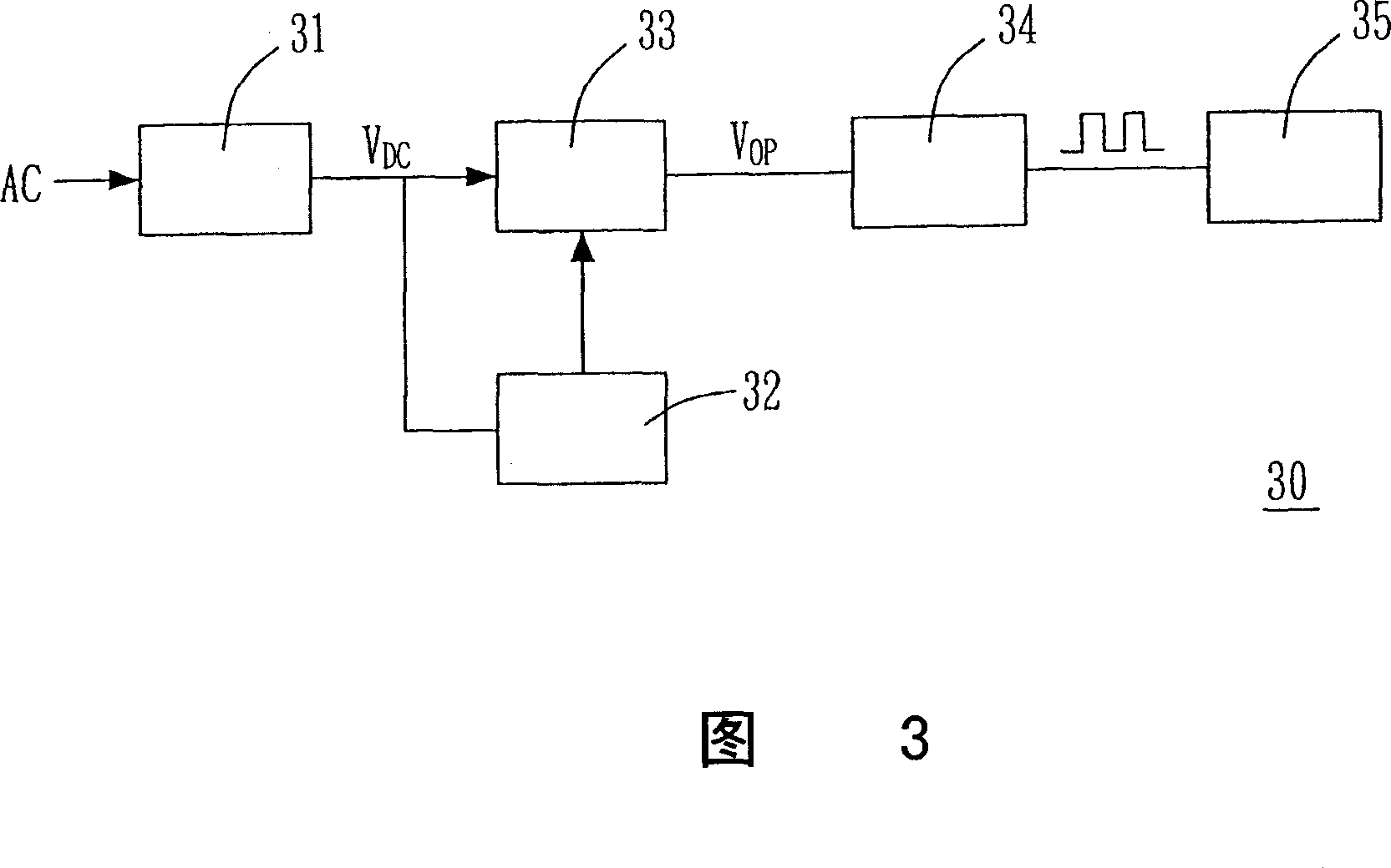
[0022] Fig. 3 is a functional block diagram of the driving circuit of the fluorescent lamp of the present invention. As shown in the figure, the driving circuit 30 includes a power factor correction stage 31 , a startup stage 32 , an isolation stage 33 , a square wave driver stage 34 and an output stage 35 . The power factor correction stage 31 receives an AC voltage AC and generates a DC voltage VDC. The start-up stage 32 is used to quickly boost the DC voltage VDC to a predetermined start-up voltage V Boost , and provide an operating voltage V op . The isolation stage 3...


PUM


Abstract

The invention discloses a drive circuit and method of fluorescent lamp. The drive circuit includes a power factor correcting class, a starting class, a square wave drive class, a separating class and a output class, thereinto the power factor correcting class converts a input alternating voltage to a direct voltage, the starting class adjusts the direct voltage to a boosting lighting direct current voltage, and parallel with the square wave drive class, the square wave drive class is connected with the separation class, and converts the lighting direct current voltage to a lighting square wave voltage, the output class is connected with the fluorescent lamp via the square wave voltage and lights the fluorescent lamp.

Description

technical field [0001] The present invention relates to a fluorescent lamp, in particular to a driving circuit and method for the fluorescent lamp. Background technique [0002] Recently, the liquid crystal display technology has been greatly improved, and it is expected to replace the cathode ray tube display as the mainstream of a new generation of displays, and this type of display requires the existence of a backlight source. As a result, various backlight sources have emerged, including mercury-containing and mercury-free fluorescent lamps, light-emitting display elements, and mercury-containing and mercury-free flat fluorescent lamps, among which various types of fluorescent lamps are most widely used. [0003] The principle of the fluorescent lamp is to use the excited gas to generate ions or excited atoms. When the excited atoms or ions return to a steady state, they will emit photons of special frequency (that is, ultraviolet light), and use the ultraviolet light to...

Claims


Application Information

Patent Timeline
IPC IPC(8): H05B41/28H05B41/295
Inventor 洪金泉黄秋凯应建平樊雨心萧昌钧
Owner DELTA ELECTRONICS INC
Learn More