Sensor

A sensor device and detector technology, applied in the field of sensing, can solve complex and expensive problems, and achieve the effect of reducing cost and power consumption

Inactive Publication Date: 2007-10-31
NXP BV
View PDF1 Cites 8 Cited by
  • Summary
  • Abstract
  • Description
  • Claims
  • Application Information

AI Technical Summary

Problems solved by technology

This is relatively complex and relatively expensive

Method used


Image

  • Sensor
  • Sensor
  • Sensor

Examples


Embodiment Construction

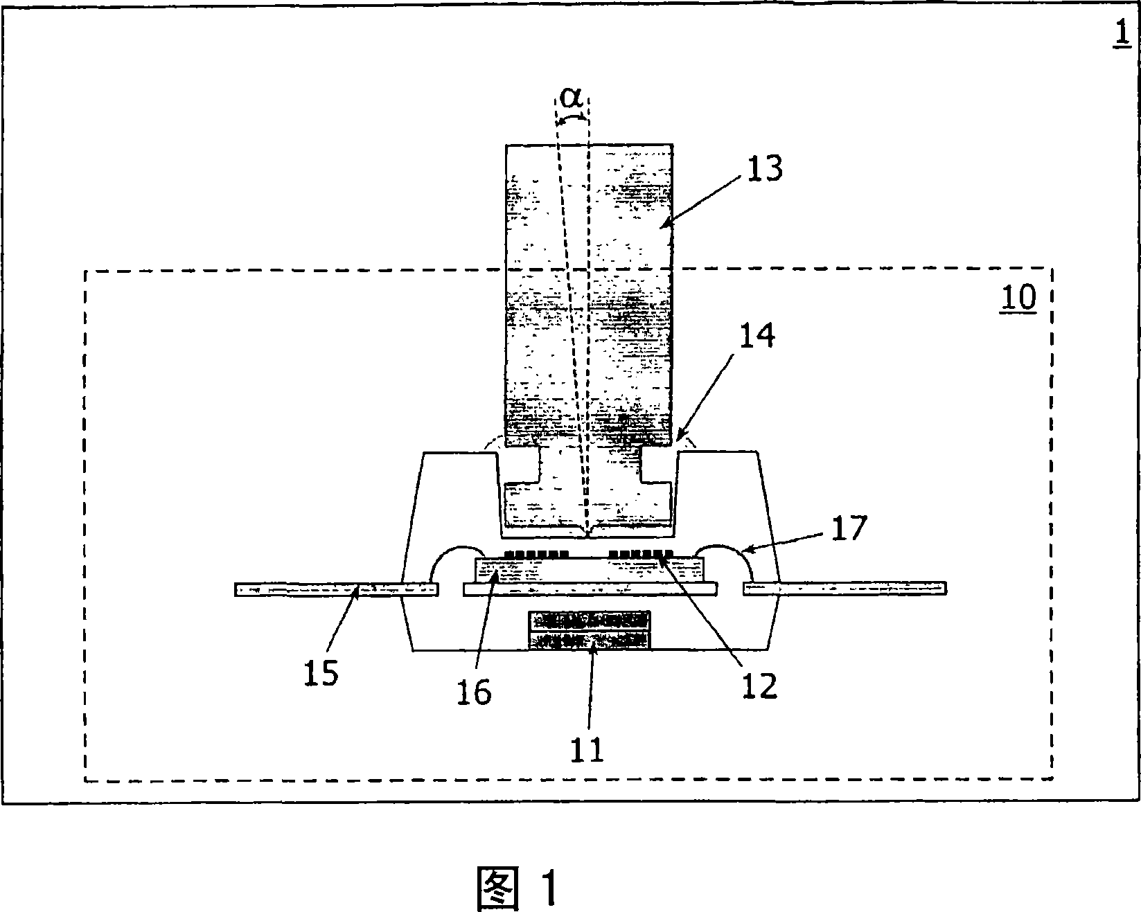
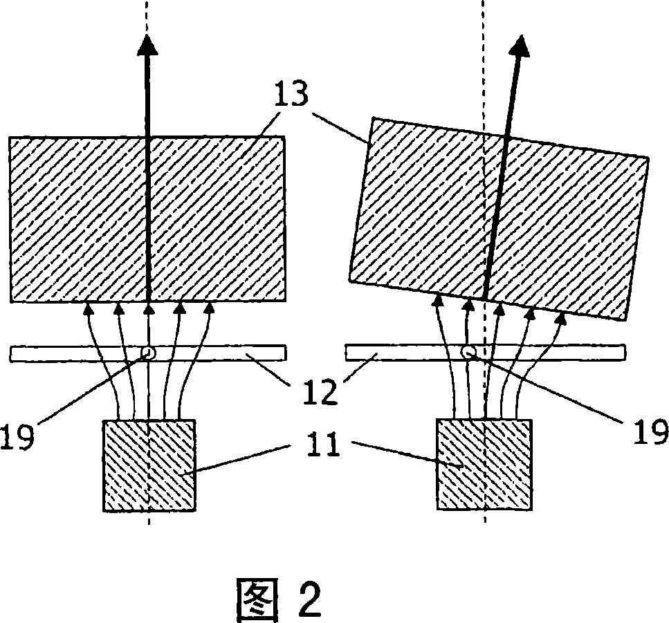
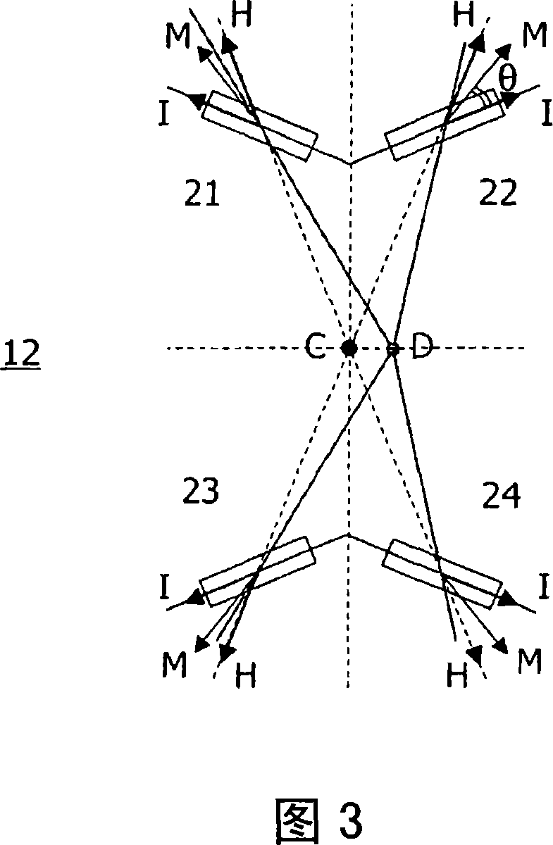
[0041] The device 1 according to the invention shown in FIG. 1 comprises a sensor arrangement 10 according to the invention. The sensor device 10 comprises a fixed object 11, such as a field generator for generating a magnetic field, such as a magnet. The sensor arrangement 10 is further adapted to detect a field detector 12 of a component of the magnetic field (as shown in Figure 3), and a movable object 13, such as a movable field conductor, such as a joystick, alters at least part of the magnetic field in response to movement. The projection of the magnetic field on the plane of the field detector is essentially a radial field. The component of the detected magnetic field is the magnetic field vector lying in the plane of the field detector. In other words, this component is the radial field vector. Changes include, for example, displacement of the radial field center 19 (as shown in FIG. 2 ).

[0042] A fixed object 11 such as a permanent magnet and a movable object 13 ...


PUM


Abstract

Devices (1) with sensor arrangements (10) comprising movable objects (13) for, in response to movements, changing magnetic fields, are provided with a field detector (12) comprising a bridge with two or more elements (21-24,31-34) and a further bridge with two or more elements (35-38) for detecting components of magnetic fields in planes of the bridges. The bridge comprises first properties depending on the movements in Z-directions and second properties depending on the movements in X-directions. The further bridge comprises third properties depending on the movements in Z-directions and fourth properties depending on the movements in Y-directions. The first and third properties indicate that the resistance values of all elements have increased or decreased with substantially the same value. The second and fourth properties indicate that the resistance values of two elements have increased with substantially the same value and that the resistance values of two other elements have decreased with substantially the same value.

Description

technical field [0001] The invention relates to a device with a sensor device, and also to a sensor device and a sensing method. [0002] Examples of such devices are portable pcs, and small handheld electronic devices such as mobile phones, personal digital assistants, digital cameras, and global positioning system devices. Background technique [0003] A prior art device is known from US 6,738,043 B2 which discloses a coordinate input device comprising a magnet for generating a magnetic field and an electromagnetic transducer for generating an output voltage. These output voltages have values ​​that vary depending on the gap between the electromagnetic transducer and the magnet. In this way, the motion of a magnet in three-dimensional space is converted into three-dimensional coordinates. [0004] The known device is disadvantageous, especially due to the fact that it requires a personal computer to evaluate the output voltage. In other words, known devices generate out...

Claims


Application Information

Patent Timeline
IPC IPC(8): G01R17/10G01R33/09G01D5/16G06F3/033G06F3/0338
CPCG01R33/096H01L2224/48091H01L2224/48247H01L2924/181H01L2924/1815
Inventor 汉斯·范宗
Owner NXP BV
Why Eureka
Try Eureka