

De-excitation system performance test analysing method and test analyzer thereof
A technology of test analysis and system performance, applied in the direction of instruments, measuring electronics, measuring devices, etc., can solve the problems that cannot fully and accurately reflect the performance of the demagnetization system, cannot meet the higher requirements for the safe operation of large-capacity generator sets, and achieve Guarantee the effect of safe and reliable operation
- Summary
- Abstract
- Description
- Claims
- Application Information
AI Technical Summary
Problems solved by technology
Method used
Image

Examples
Embodiment 1
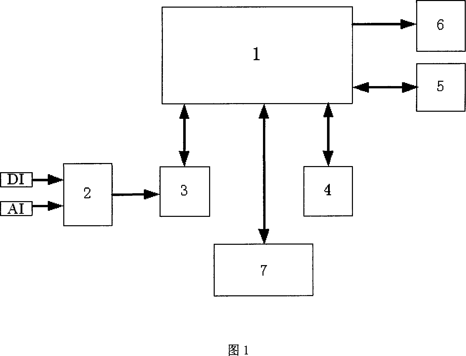
[0049] Embodiment 1, as shown in Figure 5, in the generator de-excitation system, the de-excitation switch voltage V1, the generator rotor winding voltage V2, the current V3 in the de-excitation resistance circuit (represented by the voltage on the shunt), and the de-excitation switch circuit Current V4 (indicated by the voltage on the shunt), current V5 in the generator rotor winding circuit (indicated by the voltage on the shunt) and other signals are connected to the input interface module 2 as the input signal AI, after isolation, filtering, and matching , rectification and other pretreatments, then sent to the signal conversion module 3 for A / D conversion and data acquisition, then sent to the computer motherboard 1, and then the operator controls the computer motherboard 1 through the input keyboard of the man-machine interface processor 4 Let the performance analysis module 7 perform energy calculation on the collected voltage and current data of each loop, perform timin...
Embodiment 2
[0050] Embodiment 2, as Fig. 5, current V3 (expressed with the voltage on the shunt) in the generator rotor winding voltage V2, the demagnetization resistance circuit, current V4 (expressed with the voltage on the shunt) in the demagnetization switch circuit, The current V5 in the generator rotor winding circuit (represented by the voltage on the shunt), the generator three-phase stator voltage (V6, V7, V8) and other signals are connected to the input interface module 2 as the input signal AI for isolation and filtering , matching, rectification, etc., and then sent to the signal conversion module 3 for A / D conversion and data acquisition, and then sent to the computer motherboard 1, and then the operator controls the computer mainframe through the input keyboard of the man-machine interface processor 4 Board 1 allows the performance analysis module 7 to perform volt-ampere correlation characteristic analysis on the collected voltage and current data of each loop, and then use ...
Embodiment 3
[0051] Embodiment 3, as shown in Figure 5, the generator rotor winding voltage V2, the current V3 (expressed with the voltage on the shunt) in the demagnetization resistance circuit, and the current V5 (expressed with the voltage on the shunt) in the generator rotor winding circuit The signal is connected to the input interface module 2 as the input signal AI, and after preprocessing such as isolation, filtering, matching, and correction, it is sent to the signal conversion module 3 for A / D conversion and data acquisition, and then sent to the computer motherboard 1. The operator controls the computer motherboard 1 through the input keyboard of the man-machine interface processor 4 to let the performance analysis module 7 perform spectrum decomposition calculation on the voltage and current data of each loop collected, and then display it on the liquid crystal display terminal of the man-machine interface processor 5 The above-mentioned collected signals will display the amplit...
PUM
 Abstract
Description
Claims
Application Information