Folding reflective single optical grating expending device

A single grating, reflective technology, used in optics, optical components, mirrors, etc., can solve the problems of large occupied space, difficult adjustment, complex optical path of ffner stretcher, etc., and achieve the effect of reducing lateral distance and compact structure.

Inactive Publication Date: 2007-11-07
SHANGHAI INST OF OPTICS & FINE MECHANICS CHINESE ACAD OF SCI
View PDF0 Cites 6 Cited by
  • Summary
  • Abstract
  • Description
  • Claims
  • Application Information

AI Technical Summary

Problems solved by technology

The reason is that the reflective single-grating stretcher is easy to adjust, fast, and the device is stable, while the ffner stretcher has a complex optical path and difficult adjustment. Therefore, in the case of meeting the overall requirements of the system, try to use a device that is easy to adjust, fast, and stable.
However, the reflective single grating stretcher currently used also has its disadvantages: first, it takes up a lot of space; second, in order to stagger the optical path in a certain position in the longitudinal direction, the longitudinal size of the grating should not be too large

Method used


Image

  • Folding reflective single optical grating expending device
  • Folding reflective single optical grating expending device
  • Folding reflective single optical grating expending device

Examples


Embodiment Construction

[0022] The present invention will be further described below in conjunction with the embodiments and accompanying drawings, but the protection scope of the present invention should not be limited thereby.

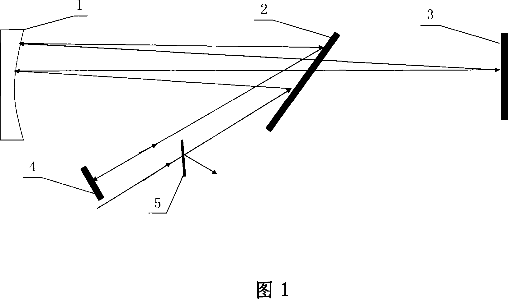
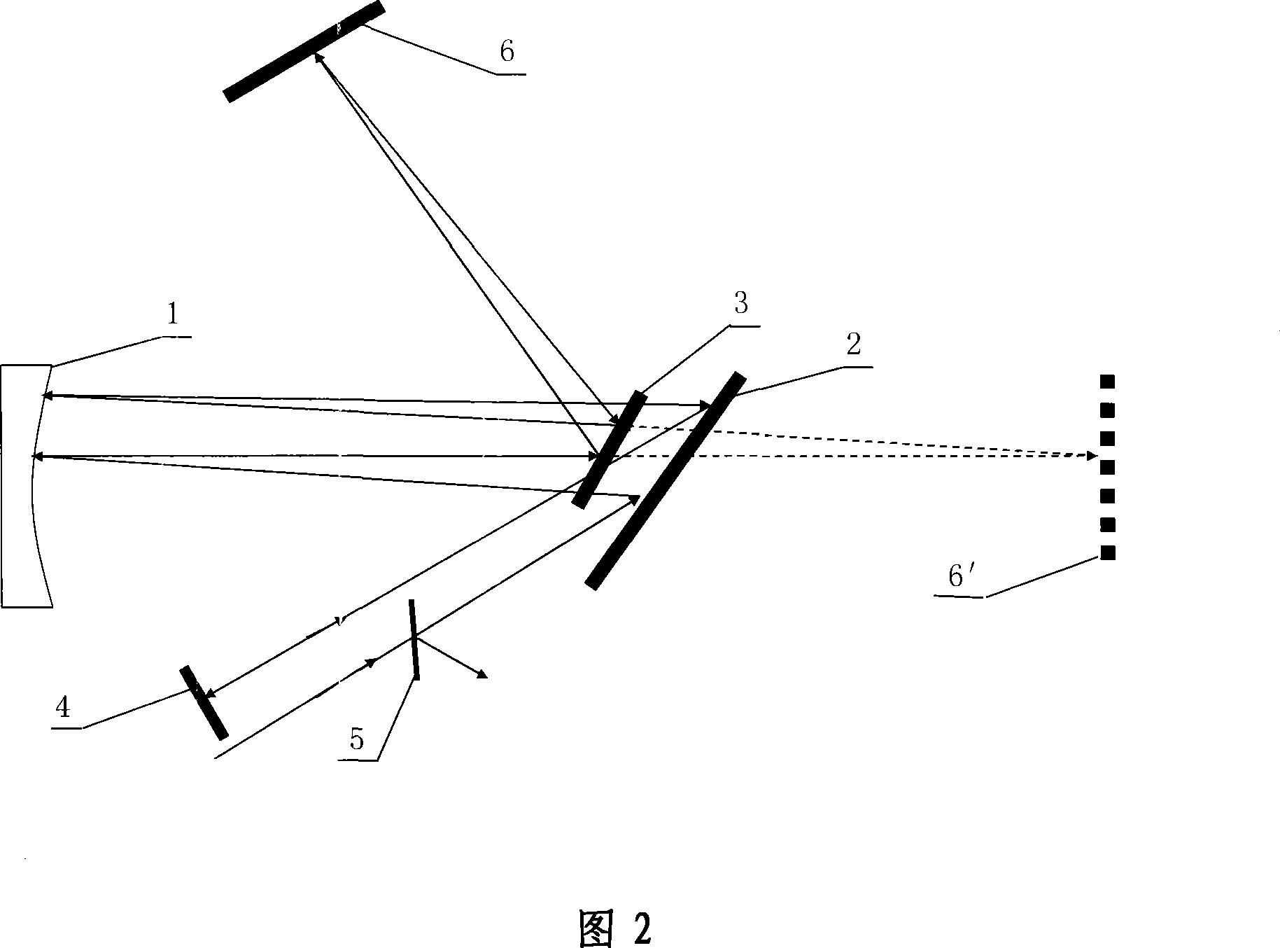
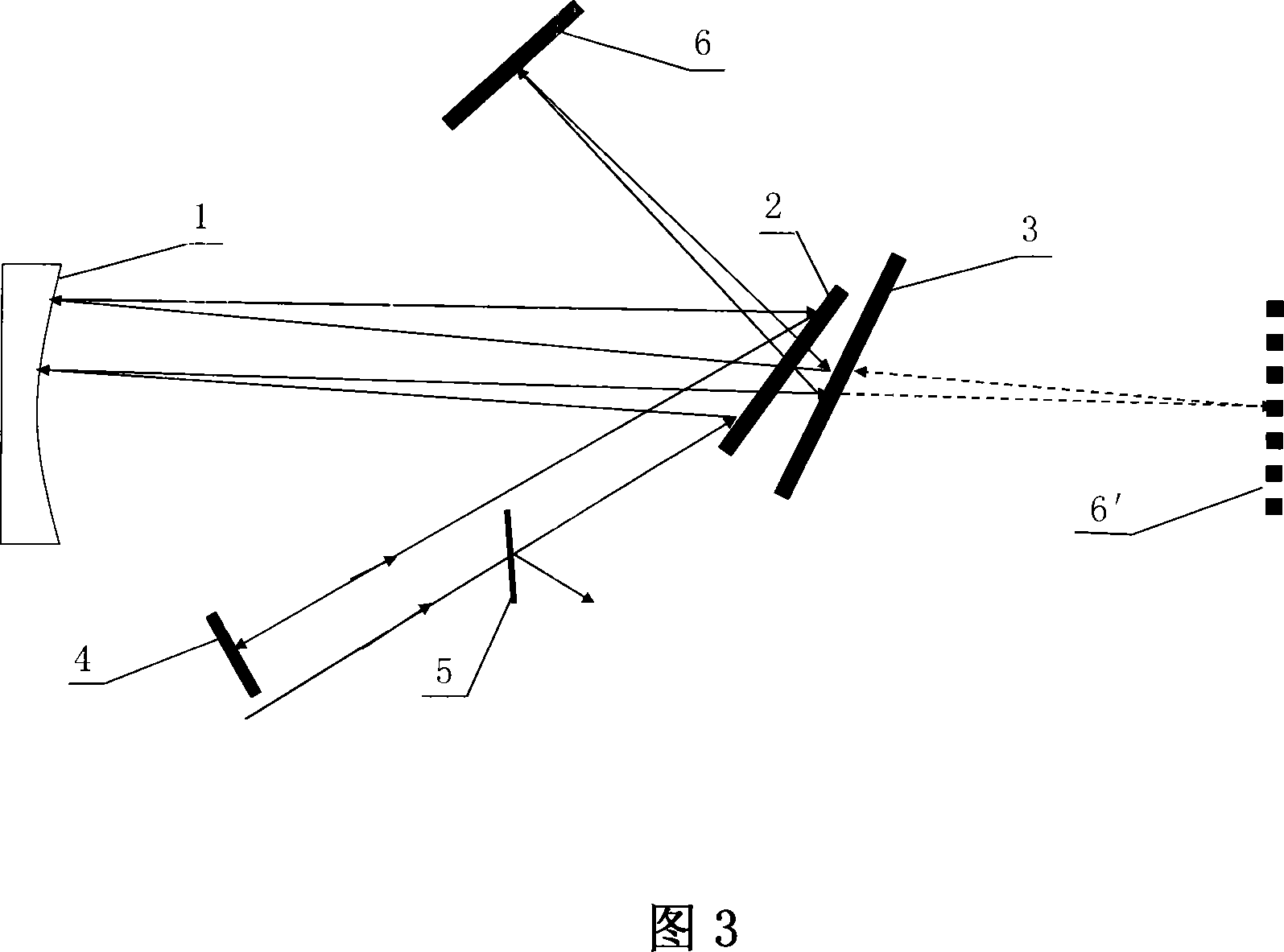
[0023] Please refer to Fig. 2 first. Fig. 2 is a schematic structural view of embodiment 1 of the folded reflective single grating stretching device of the present invention. It can be seen from the figure that the composition of embodiment 1 of the folded reflective single grating stretching device of the present invention includes cylindrical concave Mirror 1, grating 2, 1 / 2λ wave plate 5, first plane reflector 3, second plane reflector 4, described 1 / 2λ wave plate 5 is located on the light path of the light beam input and output of the device, its features Because there is also a third plane reflector 6, the first plane reflector 3 is located on the optical axis between the cylindrical concave reflector 1 and the grating 2 and is close to the grating 2, the first plane re...


PUM


Abstract

The invention relates to folded reflecting single grating spreading device. It includes column type concave mirror, grating, 1 / 2 lambada wave plate, the first and second plane reflecting mirror. The 1 / 2 lambada wave plate is set on the light beam input and output way. Its feature is that it has the third plane reflecting mirror. The first plane reflecting mirror is set at the optical axis between the column type concave mirror and the grating and close to the latter; or it is set at their optical axis extending line. The first plane reflecting mirror image about the third one is set at the focal plane of the column type concave mirror. The included angle between the first plane reflecting mirror and the optical axis is 45-90 degree. The invention has the advantages of compact structure, flexible using. And it can satisfy the demand of laser pulse big spreading ratio for high power large energy super strength super short laser system.

Description

technical field [0001] The invention relates to an ultra-intensive ultra-short laser, which is a reflective single-grating stretching device used for folding chirped pulses of a high-power, high-energy ultra-short laser system, and is mainly suitable for high-energy (200-2000 joules) ultra-short ( 10 -15 ~10 -12 seconds) Super (10 12 ~10 15 Watts) Pulse stretching of laser systems. Background technique [0002] Chirped Pulse Amplification (CPA for short) and Optical Parametric Chirped Pulse Amplification (OPCPA for short) are currently the classic methods for obtaining ultrashort and ultra-intense laser pulses, and have been widely used to build multiple terawatts (i.e. 10 12 W, abbreviated as TW) class laser system and petawatt (ie 10 15 W, abbreviated as PW) class laser system. It first uses a stretcher to introduce a certain amount of chirp to the femtosecond or sub-picosecond laser pulse to widen the pulse and inject it into a high-gain preamplifier. When the puls...

Claims


Application Information

Patent Timeline
Patent Type & Authority Applications(China)
IPC IPC(8): G02B27/09G02B5/08
Inventor 杨庆伟郭爱林谢兴龙
Owner SHANGHAI INST OF OPTICS & FINE MECHANICS CHINESE ACAD OF SCI
Why Eureka
Try Eureka