Hydraulic circuit arrangement, in particular for the drive of concrete distributor masts

A line layout and drive device technology, applied in the field of hydraulic loads, can solve problems such as lack of oil

Inactive Publication Date: 2007-11-07
PUTZMEISTER AG
View PDF1 Cites 9 Cited by
  • Summary
  • Abstract
  • Description
  • Claims
  • Application Information

AI Technical Summary

Problems solved by technology

This means that when the pressure difference set by means of the spring is exceeded, the adjusting mechanism of the regulating pump is temporarily moved in the closing direction by the directional valve of the delivery rate regulator and thus causes a lack of oil

Method used


Image

  • Hydraulic circuit arrangement, in particular for the drive of concrete distributor masts
  • Hydraulic circuit arrangement, in particular for the drive of concrete distributor masts
  • Hydraulic circuit arrangement, in particular for the drive of concrete distributor masts

Examples


Embodiment Construction

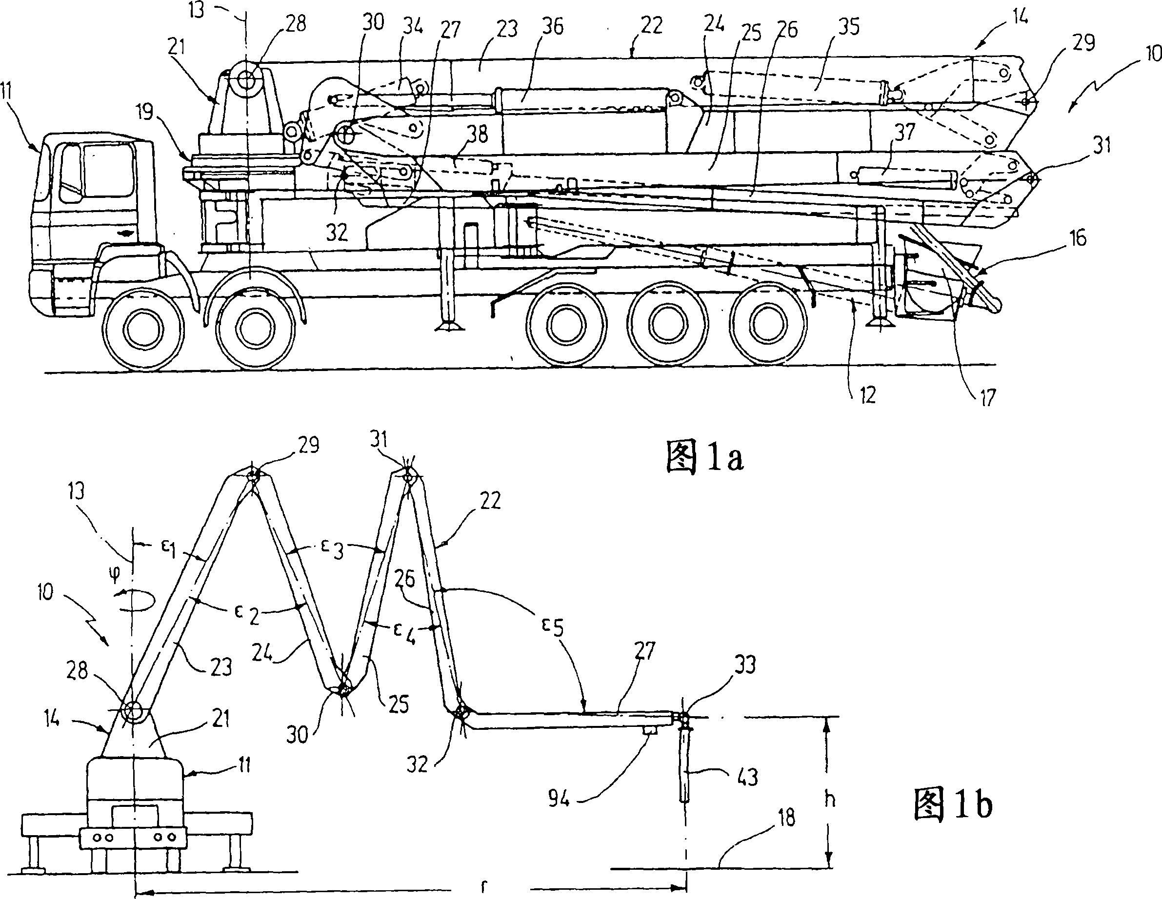
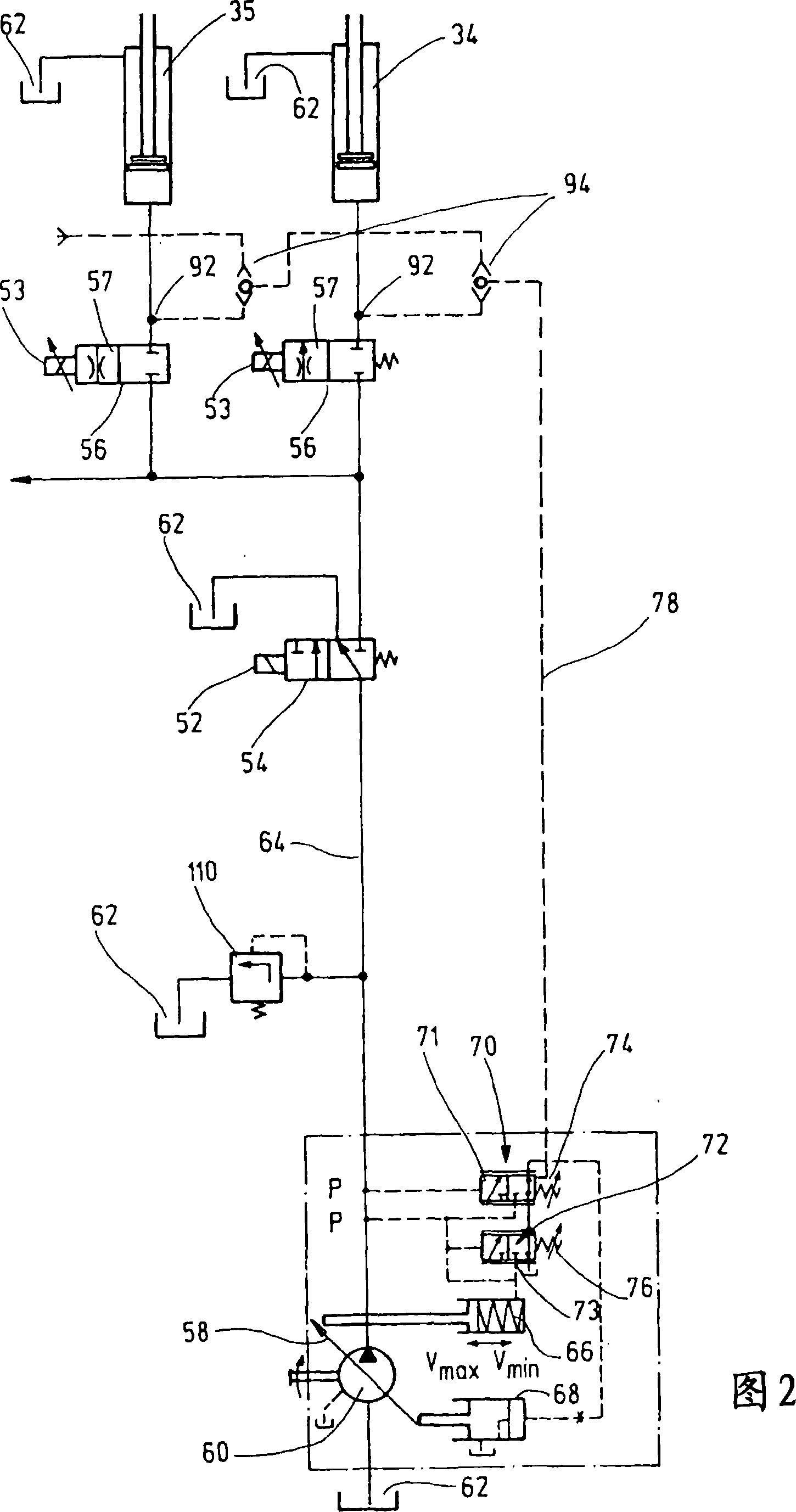
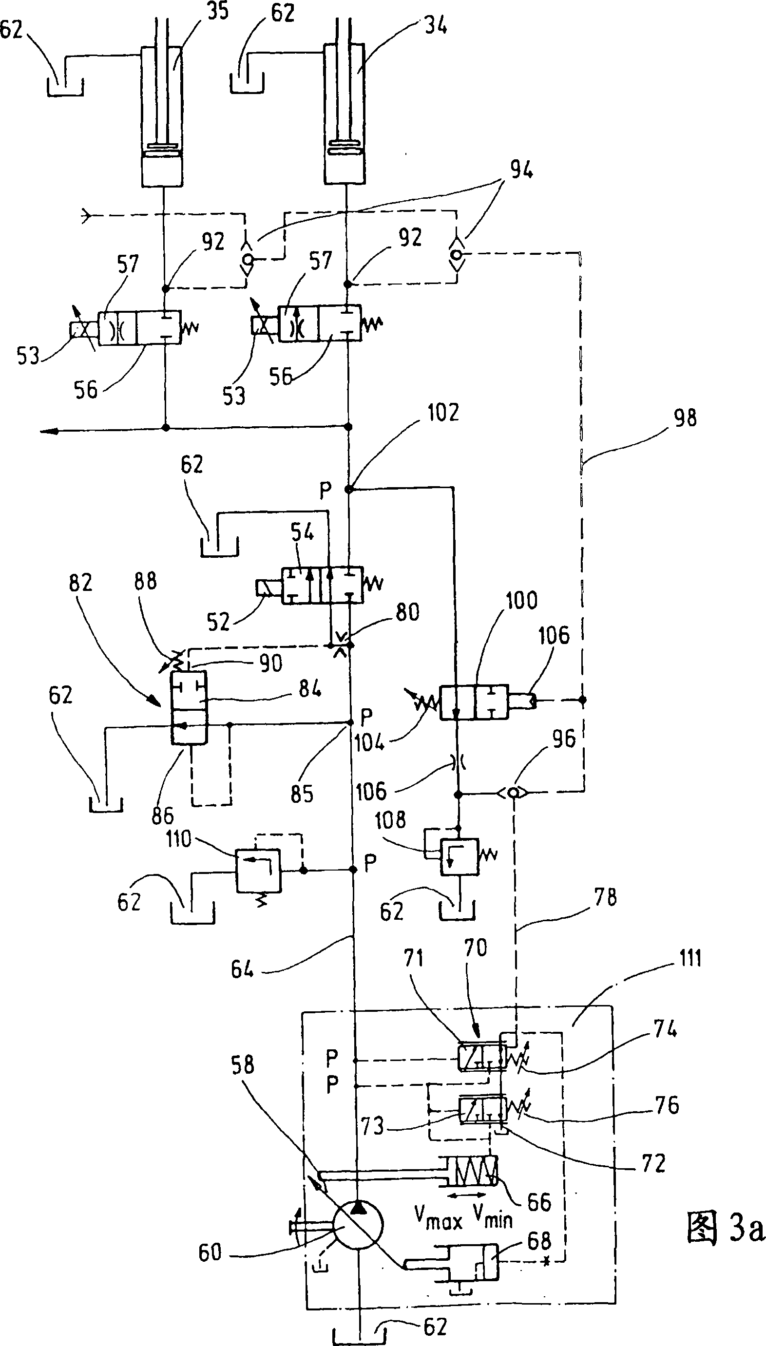
[0022] The hydraulic wiring arrangement shown in FIGS. 2 to 4 can be used, for example, to control the drive unit designed as hydraulic cylinders 34 to 38 of the self-propelled coagulation pump distribution boom 14 .

[0023] For illustration, Figures 1 a and b show an example of a self-propelled coagulation pump 10 comprising a transport vehicle 11, a mud pump 12, for example designed as a double-cylinder piston pump, and a concrete delivery pipe rotatable about a vertical axis 13 fixed on the vehicle Concrete placing boom 14 of 16 brackets. The liquid concrete that is continuously added into the feed hopper 17 during concrete pouring is delivered to a concrete pouring point 18 far away from the parking position of the vehicle 11 through the concrete delivery pipe 16 .

[0024] The distribution boom 14 is composed of a rod base 21 that can be rotated by an angle p around the vertical axis 13 by means of a hydraulic rotary drive device 19, and a hinged rod 22 that can rotate o...


PUM


Abstract

A faucet includes a faucet body, and a switching device including a switching valve mounted on the water outlet pipe of the faucet body, and a control valve adjustably mounted on the switching valve and connected to a shower head. Thus, the valve seat of the control valve is rotated to change and control the water outlet modes of the faucet exactly, thereby enhancing the switching function and working efficiency of the faucet. In addition, the faucet body only needs to provide a single screw bore for mounting the switching device without having to provide two screw bores which have to align with each other, thereby facilitating fabrication of the faucet, and thereby decreasing the costs of fabrication.

Description

technical field [0001] The invention relates to a hydraulic line layout system especially for a concrete placing boom drive, comprising: at least one hydraulic load connected to the pressure outlet of a hydraulic regulating pump on the inlet side through an oil supply pipe; at least one hydraulic load arranged in the oil supply pipe A proportional valve for each load, which cuts off the oil supply pipe in its rest position and constitutes a throttle orifice with variable opening cross-section in its working position; Switching unit connected to the oil tank in the state and connected to the at least one load in the working position; an adjustment mechanism arranged in the regulating pump, which is controlled by means of a delivery rate regulator arranged in the pump branch line, wherein the delivery rate regulator Consists of a directional valve, one pilot inlet of which is applied to the pump pressure present at the regulating pump pressure outlet and whose opposite pilot inl...

Claims


Application Information

Patent Timeline
IPC IPC(8): F15B11/16
CPCF15B2211/413F15B11/055F15B2211/20553F15B2211/6054F15B11/165F15B2211/46F15B2211/40515F15B2211/651F15B2211/455F15B2211/426F15B2211/253E04G21/0436F15B11/16
Inventor P·冯博伊曼H·本克特W·明岑迈尔
Owner PUTZMEISTER AG
Why Eureka
Try Eureka