

Seal structure of rolling bearing
A sealing device and rolling bearing technology, applied in the directions of engine sealing, bearings, ball bearings, etc., can solve problems such as high torque, and achieve the effect of reducing torque and improving sealing.
- Summary
- Abstract
- Description
- Claims
- Application Information
AI Technical Summary
Problems solved by technology
Method used
Image

Examples
Embodiment 1
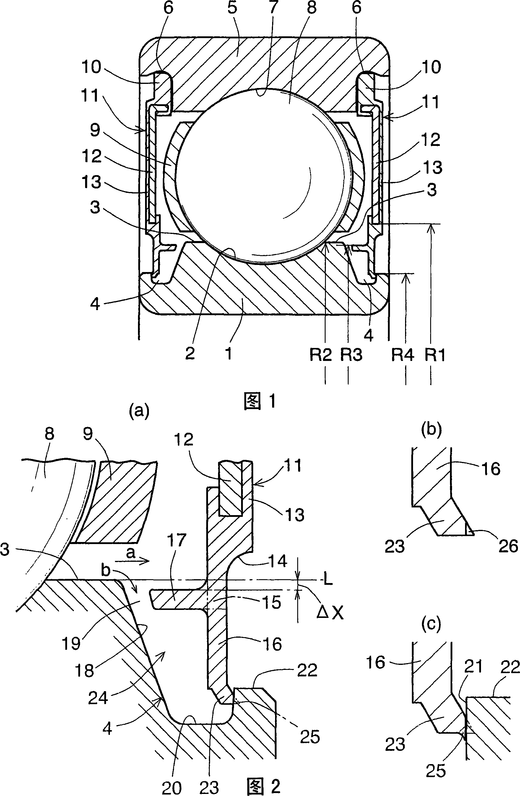
[0063]The rolling bearing of Embodiment 1 shown in FIGS. 1 and 2 has circumferential seal grooves 4 formed in lands 3 on both sides of raceway grooves 2 formed in the radially outer surface of inner ring 1 . Seal member fixing grooves 6 are formed in the radially inner surface of the outer ring 5 so as to face the corresponding seal grooves 4 . Track grooves 7 are formed in the radially inner surface of the outer ring 5 so as to face the track grooves 2 . Balls 8 are arranged between the raceway grooves 2 and 7 . The balls 8 are circumferentially separated from each other by a predetermined distance by a cage 9 .
[0064] An annular sealing member 11 is provided between each sealing groove 4 and the corresponding sealing member fixing groove 6 . The sealing member 11 is formed by molding synthetic rubber on the metal core 12 . Their outer edges 10 are fitted in and fixed to the respective seal member fixing grooves 6 . The inner diameter R1 of the metal core 12 is larger t...
Embodiment 2
[0086] The sealing device of the second embodiment shown in FIG. 5 is basically the same as that of the first embodiment. The difference is that the radial position of the branch portion 15 is determined above the extension L of the guide surface 3 and most of the auxiliary lip 17 is located above the extension L (ie, radially outside the sealing member 11 ). The radius R3 of the largest diameter portion of the auxiliary lip 17 is greater than the radius R2 of the guide surface 3 . With this configuration, although the volume of the grease pool 24 is increased, a problem arises that the end surface of the auxiliary lip 17 becomes an obstacle to the flow of grease from the guide face 3 to the radially outer surface of the auxiliary lip 17 . In order to avoid this problem, on the tip of the lip 17, a tapered surface 27 having an inclination angle θ of not less than 90° with respect to the guide surface 3 is formed.
[0087] The radially inner surface of the auxiliary lip 17 is ...
Embodiment 3 and 4
[0091] Embodiment 3 shown in FIG. 7 and Embodiment 4 shown in FIG. 8 were invented before Embodiments 1 and 2. FIG. They are disclosed as comparative examples of Examples 1 and 2.
[0092] In Embodiment 3 shown in FIG. 7, each seal member 11 has only the main seal lip. The main sealing lip 16 has a constant width and is formed at its distal end with a transverse end surface 30 . The outer corners of the end surface 30 are in contact with the outer groove wall 21 of the sealing groove 4 to define a contact seal 25 . This embodiment differs from embodiments 1 and 2 in that no auxiliary lip is provided.
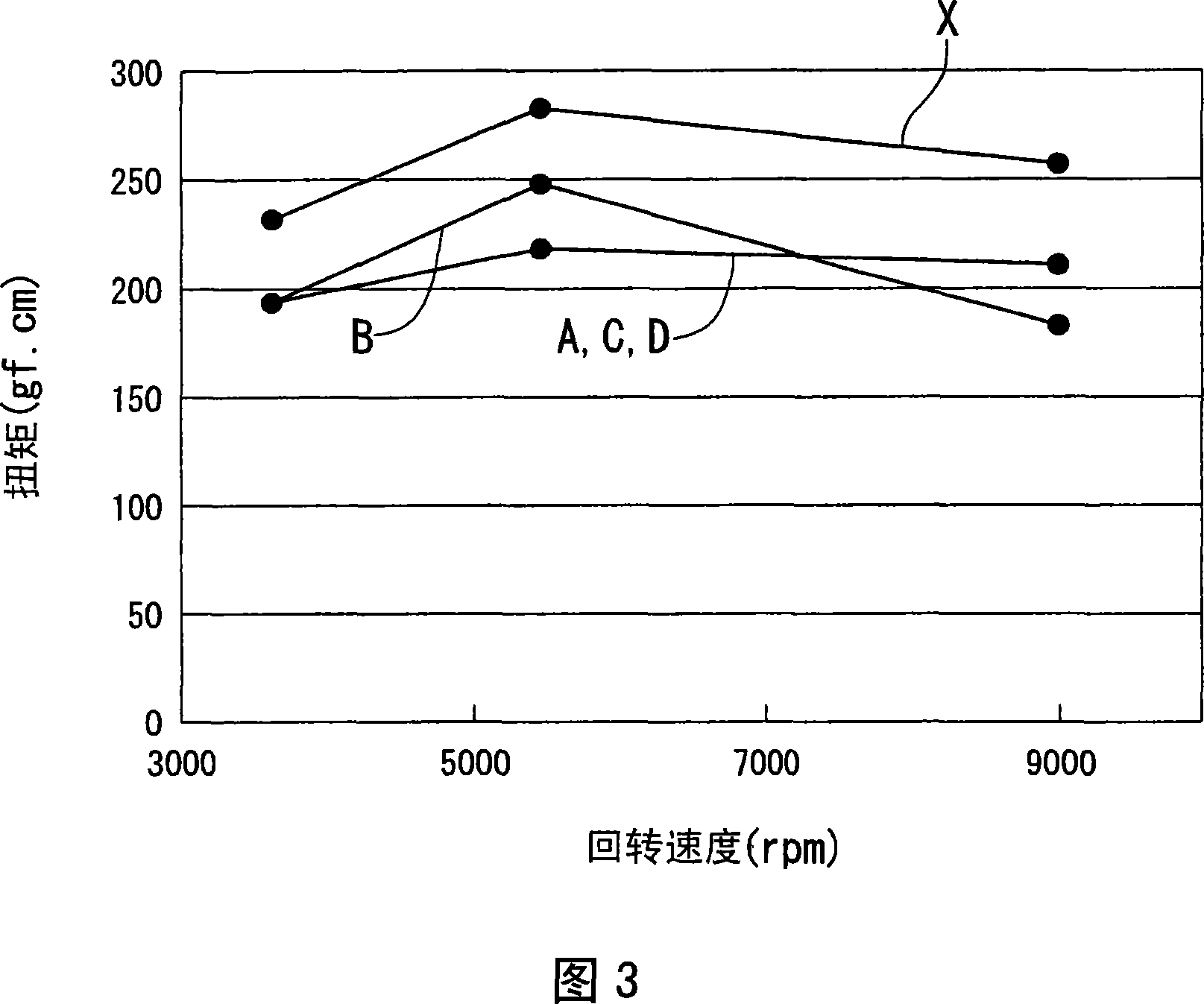
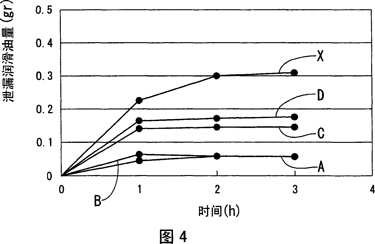
[0093] It was confirmed that when the interference of the main lip 16 was set substantially the same as in Embodiments 1 and 2, the torque value C was substantially the same as the value A in FIG. 3 . As shown by the letter C in Fig. 4, the airtightness is about 1 / 2 that of the existing product X. Therefore, it was found that the airtightness was inferior to A and B. This m...
PUM
 Abstract
Description
Claims
Application Information