Single mode, compound-split transmission with dual mechanical paths and fixed reduction ratio
A mechanical transmission, path technology, applied in mechanical equipment, elements with teeth, the arrangement of multiple different prime movers of general power units, etc., can solve problems such as loss of available energy
- Summary
- Abstract
- Description
- Claims
- Application Information
AI Technical Summary
Problems solved by technology
Method used
Image

Examples
no. 1 example
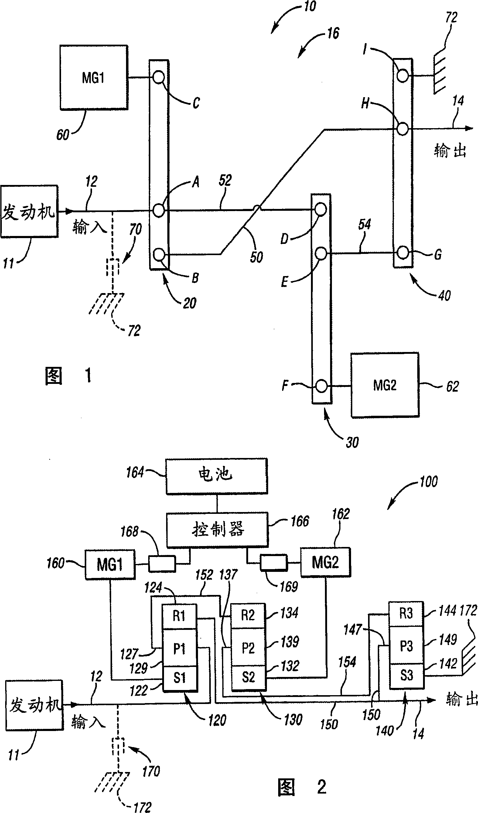
[0042] The variator 10 shown in stick diagram form in FIG. 1 can be realized by a number of alternative design embodiments, including the embodiments shown in stick diagrams in FIGS. 2 and 3, which are of longitudinal design. FIG. 2 shows a transmission 100 designed to receive at least a portion of the drive power from the engine 11 . The engine 11 has an output shaft serving as the input member 12 of the transmission 100 . The output member 14 of the transmission 100 is coupled with a final drive unit (not shown) to deliver drive power to the vehicle wheels. Transmission 100 includes 3 simple planetary gear sets. The first planetary gear set 120 includes a sun gear member 122 (designated S1), a ring gear member 124 (designated R1), and a carrier member 127 that rotatably supports a number of planet gears 129 (designated P1), which Gear 129 is in meshing engagement with the sun gear member 122 and the ring gear member 124 .
[0043] The transmission 100 also includes a seco...
no. 2 example
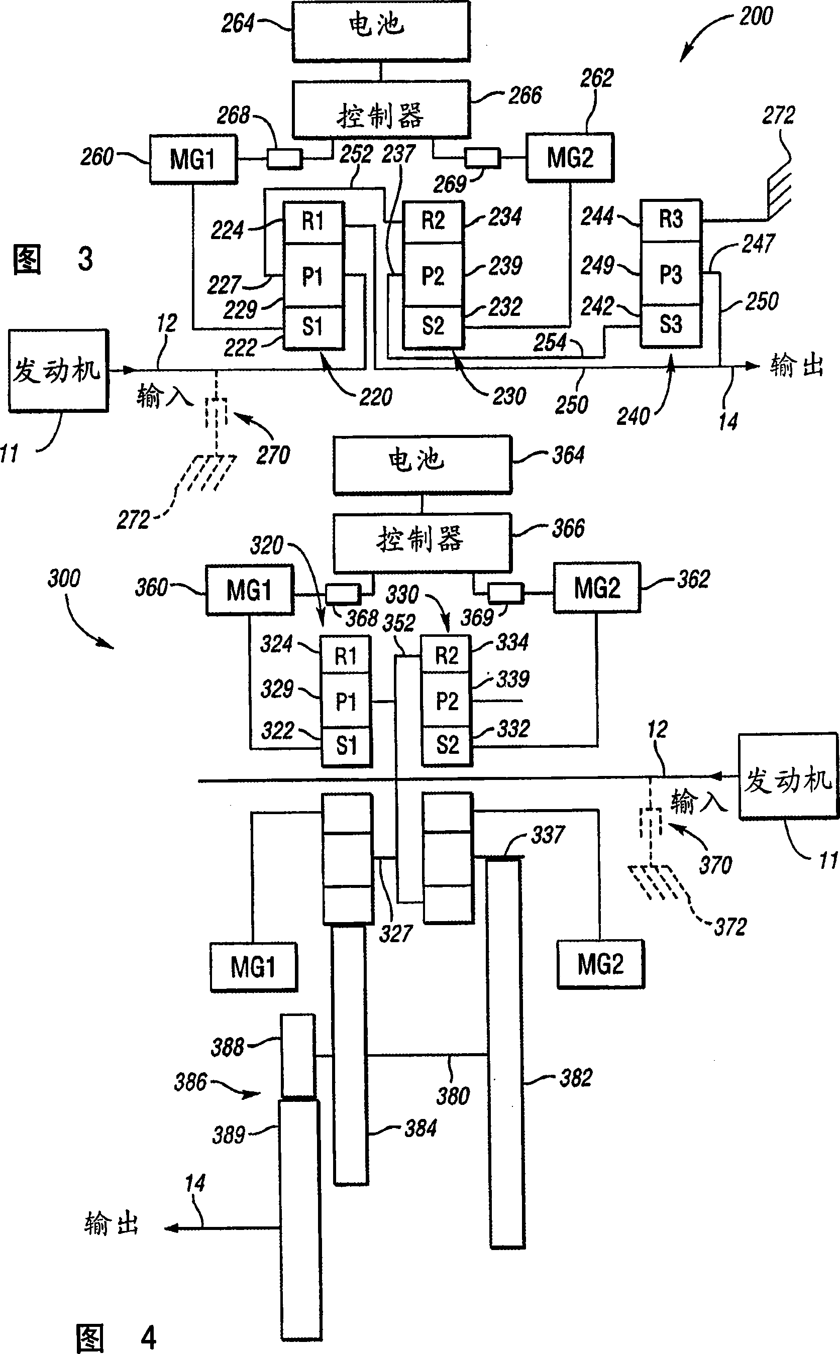
[0051] The stick diagram of FIG. 3 embodying the stick diagram 16 of FIG. 1 is similar to the stick diagram of FIG. 2 except that the reduction gear connection is changed to obtain a higher reduction ratio. FIG. 3 shows a transmission 200 designed to receive at least a portion of the drive power from the engine 11 . The engine 11 has an output shaft serving as the input member 12 of the transmission 200 . The output member 14 of the transmission 200 is coupled with a final drive unit (not shown) to deliver drive power to the vehicle wheels. Transmission 200 includes 3 simple planetary gear sets. The first planetary gear set 220 includes a sun gear member 222 (designated S1 ), a ring gear member 224 (designated R1 ), and a carrier member 227 that rotatably supports a number of planet gears 229 (designated P1 ), which Gear 229 is in meshing engagement with the sun gear member 222 and the ring gear member 224 .
[0052] The transmission 200 also includes a second planetary gea...
no. 3 example
[0060] FIG. 4 is another embodiment of an electromechanical transmission 300 within the scope of the present invention. The transmission 300 is of transverse design using a transfer shaft with transfer gears including reduction gears to provide a reduction ratio in the second mechanical power path. Thus, the third lever 40 of FIG. 1 is replaced by a transmission shaft and a transmission gear described below.
[0061] The transmission 300 is designed to receive at least a portion of driving power from the engine 11 . The engine 11 has an output shaft serving as the input member 12 of the transmission 300 . The output member 14 of the transmission 300 is coupled with a final drive unit (not shown) to deliver drive power to the vehicle wheels. Transmission 300 includes 2 simple planetary gear sets. The first planetary gear set 320 includes a sun gear member 322 (designated S1), a ring gear member 324 (designated R1), and a carrier member 327 that rotatably supports a number of...
PUM
 Abstract
Description
Claims
Application Information
 - Generate Ideas
- Intellectual Property
- Life Sciences
- Materials
- Tech Scout
- Unparalleled Data Quality
- Higher Quality Content
- 60% Fewer Hallucinations
Browse by: Latest US Patents, China's latest patents, Technical Efficacy Thesaurus, Application Domain, Technology Topic, Popular Technical Reports.
© 2025 PatSnap. All rights reserved.Legal|Privacy policy|Modern Slavery Act Transparency Statement|Sitemap|About US| Contact US: help@patsnap.com