Laser diode drive circuit

A laser diode and driving circuit technology, applied in circuits, lasers, laser parts and other directions, can solve the problems of long feedback path, large time constant, difficult circuit matching, etc., to eliminate the response speed, easy circuit design, and time constant. small effect

Inactive Publication Date: 2007-11-14
MITSUBISHI ELECTRIC CORP
View PDF1 Cites 9 Cited by
  • Summary
  • Abstract
  • Description
  • Claims
  • Application Information

AI Technical Summary

Problems solved by technology

However, because the feedback path is longer, the time constant becomes larger
Therefore, the response speed of the active matching operation to eliminate the noise from the laser diode is slow, and the noise cannot be reliably eliminated.
In addition, it is very difficult to perform circuit matching in a high-frequency region such as 10Gbps

Method used


Image

  • Laser diode drive circuit
  • Laser diode drive circuit
  • Laser diode drive circuit

Examples


Embodiment Construction

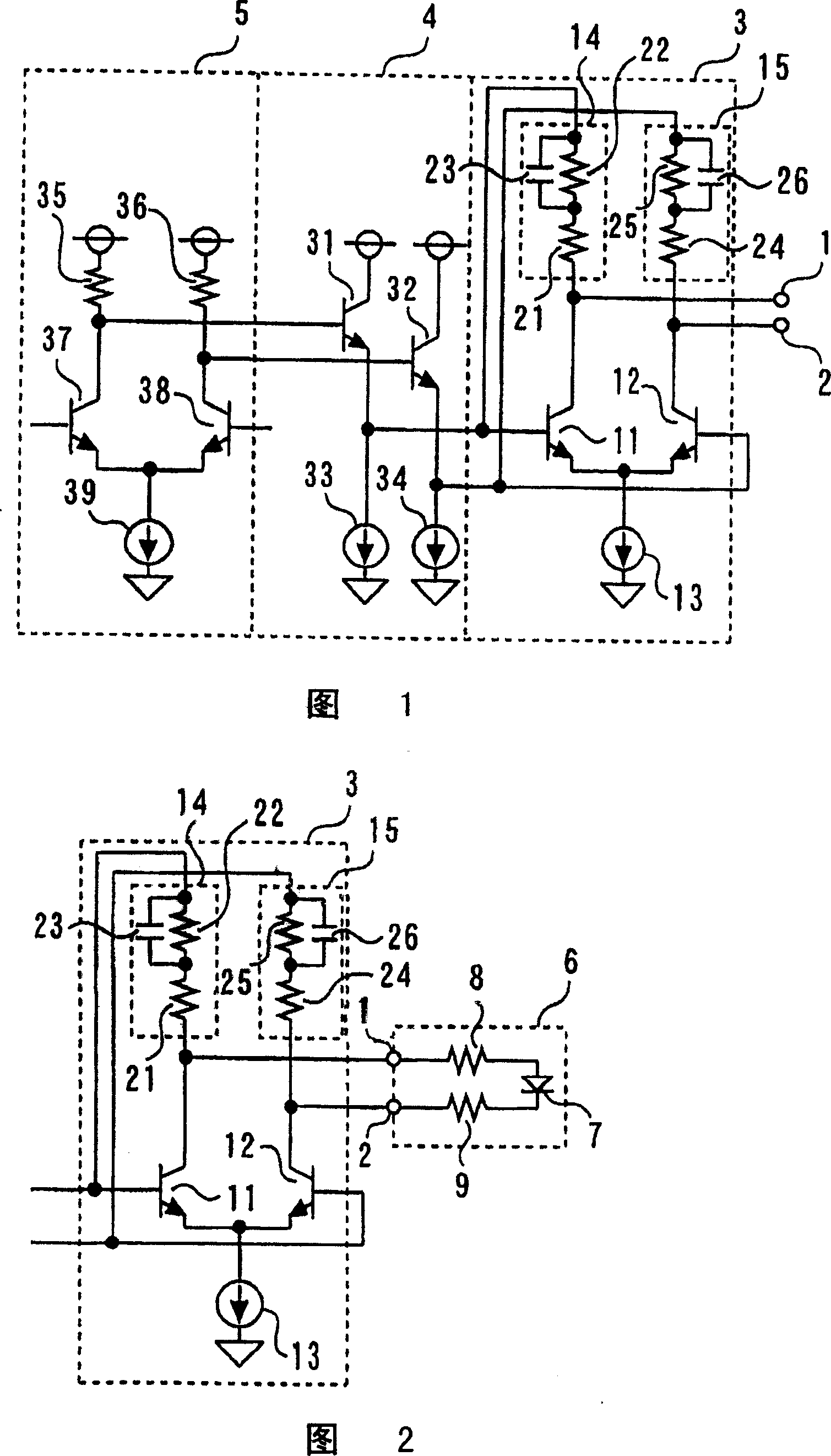
[0023] Fig. 1 is a circuit diagram showing a driving circuit according to a first embodiment of the present invention. In addition, FIG. 2 is a circuit diagram showing a TOSA to which the driving circuit of FIG. 1 is connected.

[0024] A drive circuit having output terminals 1, 2, a final stage amplifying circuit 3, a first emitter follower circuit 4 arranged in a preceding stage of the final stage amplifying circuit 3, and an amplifier arranged in a preceding stage of the first emitter follower circuit 4 Circuit 5.

[0025] On the other hand, TOSA 6 has laser diode 7 , matching resistor 8 connected to the anode of laser diode 7 , and matching resistor 9 connected to the cathode of laser diode 7 .

[0026] The final stage amplifier circuit 3 has: a first transistor 11 , a second transistor 12 , a constant current circuit 13 , a first high-pass filter 14 , and a second high-pass filter 15 . Then, the collector of the first transistor 11 is connected to the anode of the laser...


PUM


Abstract

Aimed is to obtain a drive circuit of a laser diode capable of surely eliminating noise and easy in circuit design. The drive circuit of a laser diode comprises a first transistor with its collector connected with an anode of the laser diode, a second transistor with its collector connected with a cathode of the laser diode, a constant current circuit connected between emitters of the first and second transistors and a ground point, a first bypass filter connected between a base and a collector of the first transistor, and a second high pass filter connected between a base and a collector of the second transistor.

Description

technical field [0001] The present invention relates to a drive circuit for driving a laser diode, in particular to a drive circuit for a laser diode that can reliably eliminate noise from the laser diode and is relatively easy in circuit design. Background technique [0002] In recent years, in communication devices using optical fibers (for example, refer to Patent Document 1), the characteristics of the transmission line to the laser diode have changed from 50Ω matching is changed to 25Ω matching. Therefore, in order to further lower the power supply voltage, it tends to keep the 25Ω of the transmission line constant and reduce or eliminate the matching resistance on the laser diode side. That is, the standardized transmission line remains unchanged at 25Ω, and the matching resistance on the laser diode side only gives the built-in resistance of the laser diode 7Ω. Therefore, since the mismatch of the matching resistance value on the laser diode side, the characteristic...

Claims


Application Information

Patent Timeline
Patent Type & Authority Applications(China)
IPC IPC(8): H01S5/042H01S5/062H04B10/00
CPCH01S5/042H01S5/0427
Inventor 高相纯东坂范雄
Owner MITSUBISHI ELECTRIC CORP
Why Eureka
Try Eureka