Fluid supply method and apparatus

A technology of liquid and supply source, applied in the field of liquid supply system, can solve the problems of difficult printing head, restricting the installation of printing head, etc., and achieve the effect of high precision

Inactive Publication Date: 2007-11-14
XAAR TECH LTD
View PDF2 Cites 18 Cited by
  • Summary
  • Abstract
  • Description
  • Claims
  • Application Information

AI Technical Summary

Problems solved by technology

However, these requirements also limit the ways in which printheads can be installed
In particular, scanning setups in which the printhead is mounted on a carriage that moves across the substrate are difficult, which also requires a carriage mechanism capable of moving both the printhead and the ink tubes

Method used


Image

  • Fluid supply method and apparatus
  • Fluid supply method and apparatus
  • Fluid supply method and apparatus

Examples


Embodiment Construction

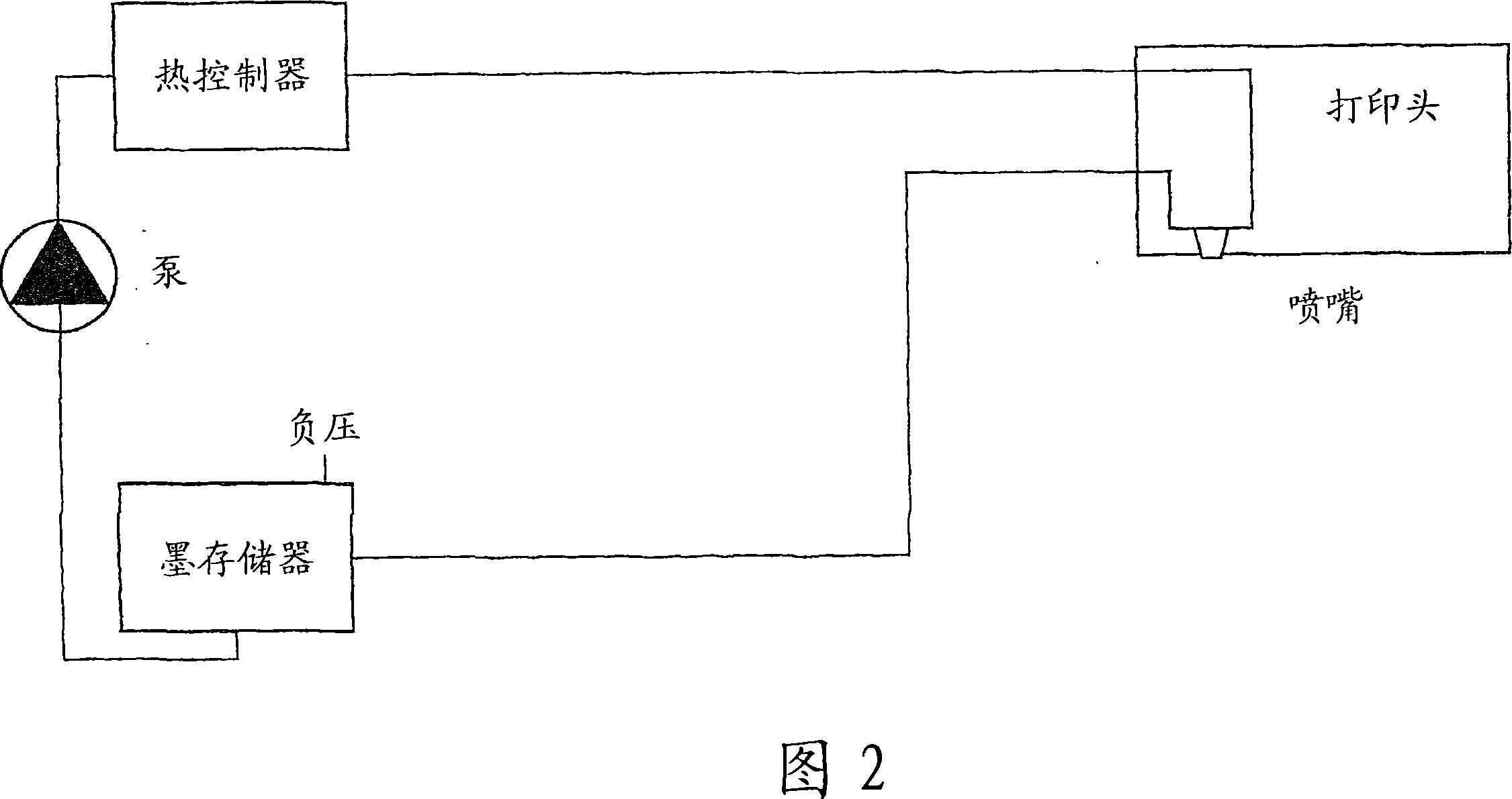
[0031] Figure 2 shows a closed, thermally controlled, recirculating-throgh-ejection chamber liquid supply system with negative pressure at the nozzle. The liquid supply system has the advantage of being completely isolated from the atmosphere (except at the nozzles) so that there is no problem of sucking in air. Moreover, the system is simple and thus low in cost. The system is also compact and flexible in terms of component arrangement, especially its height. The pump generates positive pressure upstream and negative pressure downstream, and the pump speed is selected to maintain flow in excess of the maximum printhead jet. The flow is typically 10 times the maximum jet rate and can be as high as 30 times the maximum jet rate.

[0032] The pumping circuit (pumping circuit) between the pump and the nozzle, including the internal flow path of the print head, is roughly symmetrical in its liquid resistance, but in order to generate the small negative pressure required at the n...


PUM


Abstract

A method and apparatus for supplying fluid to a deposition device or printhead using the through flow principle. The pressure of fluid entering and exiting the printhead is controlled directly at the printhead by respective pressure controllers, preferably a transducer and control system or a weir. The pressure controllers can be integrated together and mounted on or further integrated with the printhead. The supply system preferably forms a closed loop including a remote reservoir, and the entire system can be arranged such that the overall free surface of fluid is exposed on average to a negative gauge pressure.

Description

technical field [0001] The present invention relates to a liquid supply system for a droplet deposition device, and in particular to an ink supply system for a drop-on-demand inkjet printhead operating according to the through-flow principle . Background technique [0002] In existing flow-through devices, ink is removed from the printhead in order to remove dirt and air bubbles that can clog the printhead nozzles, and to remove heat from the ink ejection mechanism that can change ink viscosity and thus affect print quality. Replenish the printhead with filtered ink at the correct temperature. Ink removal and replenishment is usually continuous, and the removed ink is filtered and cooled before being fed back to the printhead. The through-flow may be restricted to the printhead manifold or may pass through the individual printhead firing chambers where the through-flow removes any dirt or air bubbles that may be present within the respective inkjet nozzles. [0003] Such ...

Claims


Application Information

Patent Timeline
Patent Type & Authority Applications(China)
IPC IPC(8): B41J2/19B41J2/20
Inventor 保罗·德鲁里斯蒂芬·坦普尔迈克尔·珀泽
Owner XAAR TECH LTD
Why Eureka
Try Eureka