Antenna having conductive planes connected by a conductive bridge

A conductive plane and antenna technology, applied in the direction of antenna, resonant antenna, antenna support/mounting device, etc., can solve the problems of unfavorable antenna and achieve the effect of improving omnidirectionality

Inactive Publication Date: 2007-11-14
KONINKLIJKE PHILIPS ELECTRONICS NV
View PDF4 Cites 1 Cited by
  • Summary
  • Abstract
  • Description
  • Claims
  • Application Information

AI Technical Summary

Problems solved by technology

[0004] This known antenna is disadvantageous especially because the ground plane works against the ground surface
Such a ground surface results in adequate antenna performance, but its relatively large

Method used


Image

  • Antenna having conductive planes connected by a conductive bridge
  • Antenna having conductive planes connected by a conductive bridge
  • Antenna having conductive planes connected by a conductive bridge

Examples


Embodiment Construction

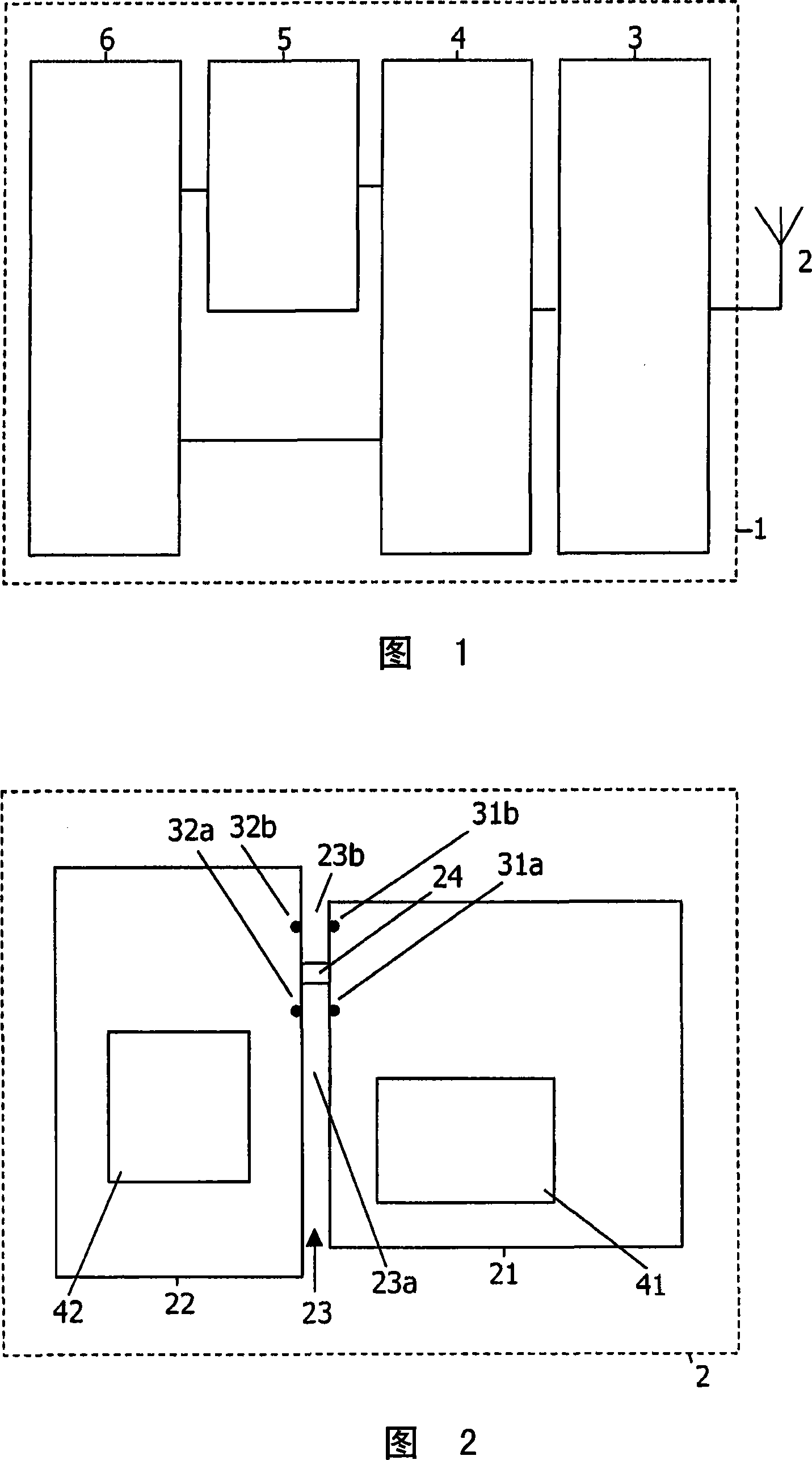
[0050] The device 1 according to the present invention shown in FIG. 1 is, for example, a home theater device, a surround sound device, a wireless headphone device, a second room wireless audio device, a biosensor device, a location tracking device, a mobile terminal and a wireless An interface comprising an antenna 2 according to the invention coupled to a radio unit 3 . The radio unit 3 is coupled to a digital signal processor 4 which is coupled indirectly to a man-machine interface 6 via a digital-to-analog converter 5 and directly without any intervening unit.

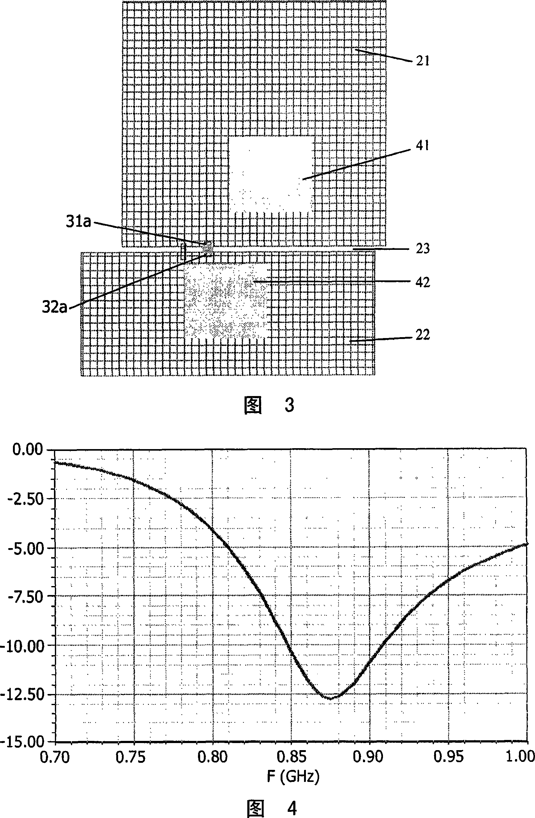
[0051] The antenna 2 according to the invention, shown more particularly in FIG. 2 , comprises a first conductive plane 21 and a second conductive plane 22 separated by a non-conductive gap 23 and conductively coupled to each other by a conductive bridge 24 . The conductive bridge 24 divides the gap 23 into a first gap 23a and a second gap 23b. The first conductive plane 21 comprises a first connection point 31a p...


PUM


Abstract

In devices comprising antennas (2) for exchanging radio frequency signals, the antennas (2) comprise two conductive planes (21,22) which comprise two connection points (31a,32a) and which are separated by gaps (23) for separating the conductive planes (21,22) from each other and which are coupled to each other by conductive bridges (24). These antennas (2) have a sufficient antenna performance, do not require power amplifiers to be over dimensioned, do not introduce extra power consumption, have sufficient bandwidth, are low cost and can easily be manufactured. The conductive planes (21,22) carry processing circuitry (41) and interfacing circuitry (42). By introducing two further connection points (31b,32b), the gaps (23) are divided into first gaps (23a) and second gaps (23b) by the conductive bridges (24) and the antennas (2) can be used in different frequency bands. The conductive planes (21,22) may make an angle with respect to each other, to allow the antennas (2) to be shaped in dependence of device constructions.

Description

technical field [0001] The invention relates to a device comprising an antenna for exchanging radio frequency signals with another device, and also to an antenna and a method. [0002] Examples of such devices are home theater devices, surround sound devices, wireless headphone devices, second room wireless audio devices, biometric sensing devices, location tracking devices, mobile terminals, and wireless interfaces. Background technique [0003] A prior art antenna is known from US 2002 / 0177416 A1 which discloses in its FIGS. 2 and 3 a ground surface 202 comprising an RF module 206 . This RF module 206 includes an RF circuit 306 mounted on a ground plane 302 incorporating a slot 304 with an open end and a closed end. As disclosed in FIG. 11 thereof, the connection points 308 , 1102 are near both sides of the slot 304 near the closed end. [0004] This known antenna is particularly disadvantageous because the ground plane operates against the ground surface. Such a ground...

Claims


Application Information

Patent Timeline
IPC IPC(8): H01Q9/24H01Q5/00H01Q5/35
CPCH01Q5/0048H01Q5/35H01Q9/24H01Q1/24H01Q1/38
Inventor A·克塞莱尔斯
Owner KONINKLIJKE PHILIPS ELECTRONICS NV
Why Eureka
Try Eureka