Electromotor safety valve

A safety valve and motor technology, applied in the direction of engine components, lift valves, electromagnets, etc., can solve the problems of reduced battery life, rising cost, installation space limitation, etc., and achieve the effect of preventing cost rise, preventing stall, and increasing degrees of freedom.

Active Publication Date: 2007-11-21
RINNAI CORP
View PDF1 Cites 8 Cited by
  • Summary
  • Abstract
  • Description
  • Claims
  • Application Information

AI Technical Summary

Problems solved by technology

If such a stall occurs, unpleasant noise with the same cycle as the drive pulse will be generated
Therefore, the commerciality of the gas appliance incorporating the motor safety valve may be damaged.
In addition, when a stall occurs, since the power consumption of the stepping motor increases during the stall, when a dry battery is used as the power supply, there is also the disadvantage t

Method used


Image

  • Electromotor safety valve
  • Electromotor safety valve
  • Electromotor safety valve

Examples


Embodiment Construction

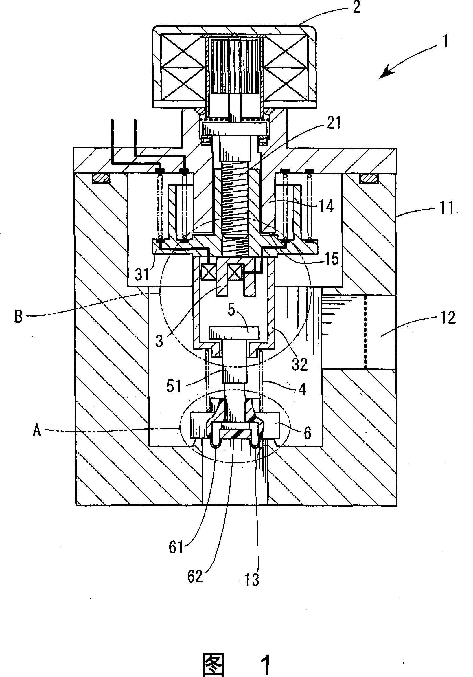
[0021] Referring to Fig. 1, 1 is an example of a motor safety valve of the present invention. An inlet 12 for inflowing gas and a valve port 13 for outflowing gas are provided on the housing 11 of the motor safety valve. The stepping motor 2 is mounted on the upper part of the casing 11 . The stepping motor 2 rotates at a rotation angle proportional to the number of input drive pulses, and can freely switch between forward and reverse rotation.

[0022] An external thread 21 is provided on the rotating shaft of the stepping motor 2 . On the other hand, 3 is a movable electromagnet held by a holder 31 screwed to the external thread 21 . The retainer 31 is inserted into the anti-rotation portion 14 to be able to move forward and backward. In addition, the lower end of the anti-rotation portion 14 functions as a stopper for the upward movement of the holder 31 . The movable electromagnet 3 is enclosed by a housing 32 fixed on a holder 31 .

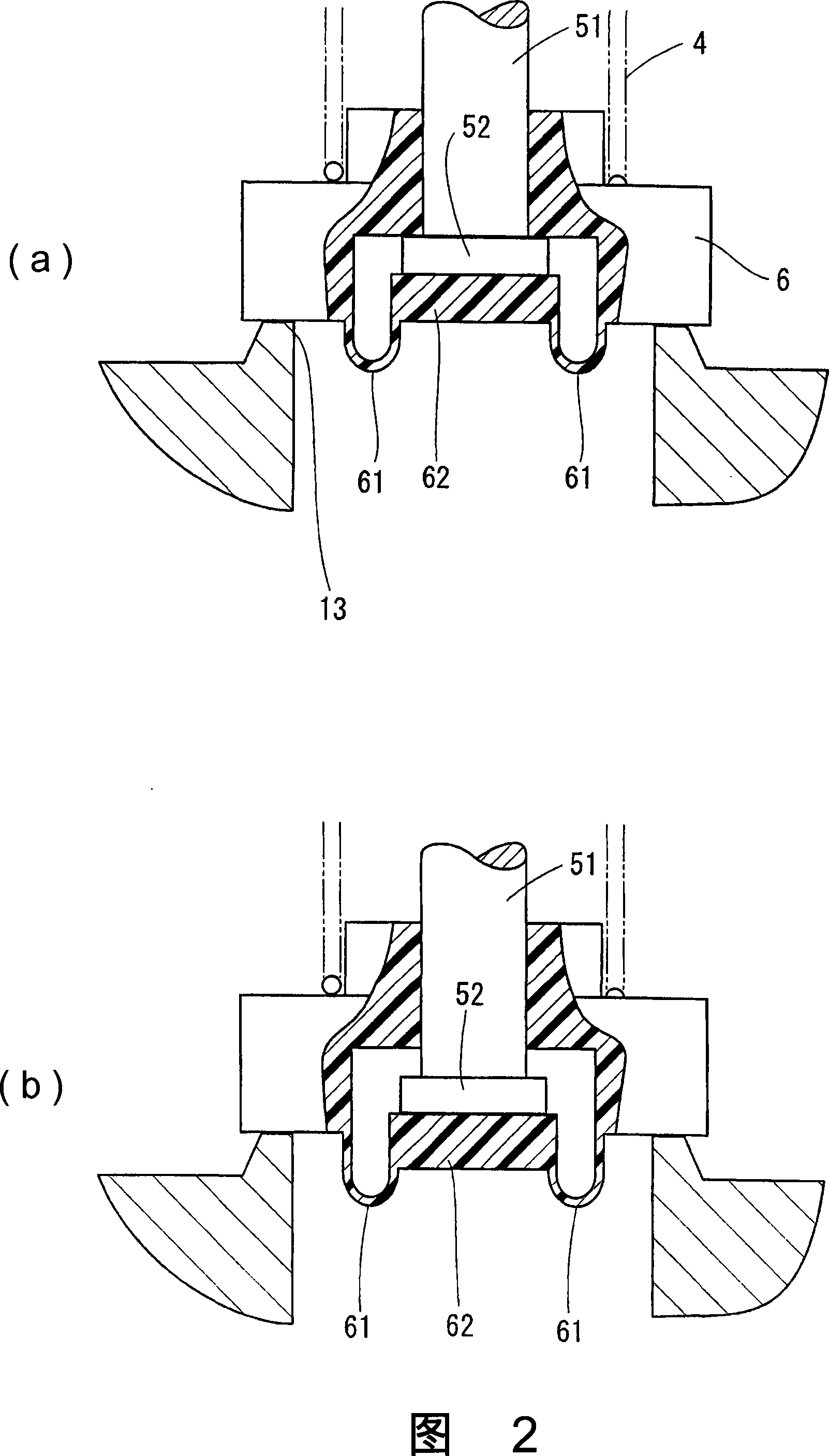
[0023] The movable iron piece 5 o...


PUM


Abstract

To prevent the occurrence of noise due to step-out without upsizing a stepping motor by limiting a load. In a motor safety valve 1 for opening a valve port 13 by pulling up a valve element 6 by a stepping motor 2 in a state that a movable iron piece 5 is attracted by a movable electromagnet 3 mounted in a holder 31, a center part 62 abutting to the lower end of a rod 51 is surrounded by an annular deformation part 61. If the movable iron piece 5 is pressed down further when the valve element 6 is opened. The center part 62 moves toward a lower place to limit the load acting on the stepping motor 2.

Description

technical field [0001] The present invention relates to pushing a movable electromagnet that moves forward and backward by a stepping motor on a movable iron piece connected to a valve core, and lifting the valve core to open while the movable electromagnet is attached to the movable iron piece. valve motor safety valve. Background technique [0002] As a conventional motor safety valve of this type, there is known a motor safety valve that has a stepping motor, a male screw member connected to the rotation shaft of the stepping motor, and a cage screwed to the male screw member. Since the cage is locked, when the rotating shaft of the stepping motor rotates forward and backward, the rotational motion of the rotating shaft is converted into linear motion, and the cage moves forward and backward. [0003] The movable electromagnet is mounted on the holder, and the rod-shaped rod is engaged with the rubber valve core of the opening and closing valve port, and a movable iron p...

Claims


Application Information

Patent Timeline
IPC IPC(8): F16K1/00F16K31/06F16K31/08
CPCF16K27/029F16K31/04F16K31/0655H01F7/16
Inventor 和田则夫清水正则水谷圭一
Owner RINNAI CORP
Why Eureka
Try Eureka