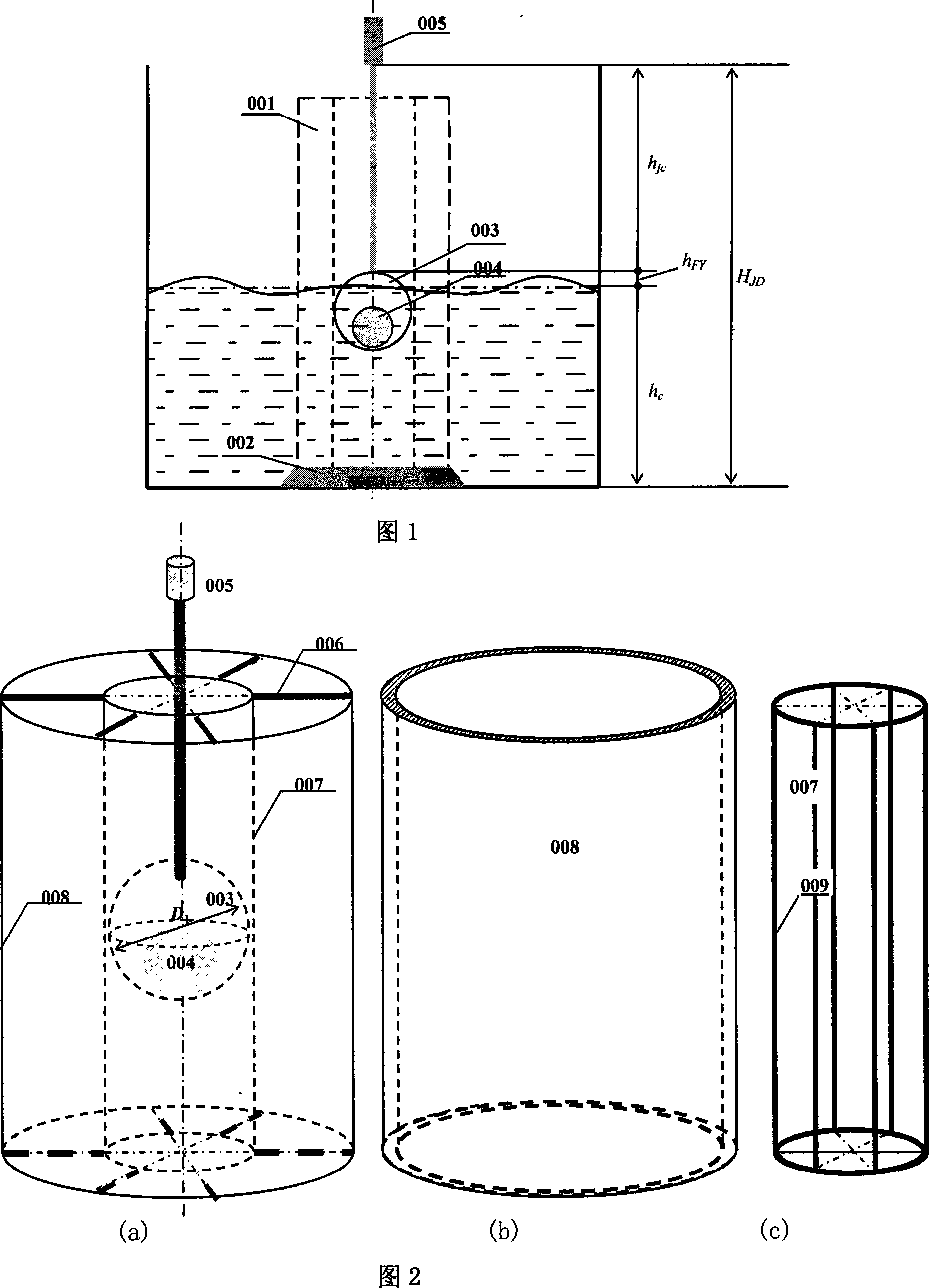
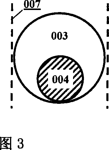
Float laser liquid-level measuring device
A technology of liquid level measurement and laser range finder, which is applied in the direction of buoy liquid level indicator, etc., and can solve the problems affecting popularization and application
- Summary
- Abstract
- Description
- Claims
- Application Information
AI Technical Summary
Problems solved by technology
Method used
Image
Examples
Embodiment 1
[0027] Water level measurement in hydrology:
[0028]In the field of hydrology and hydrology, it is very important to measure changes in the water level of rivers, lakes or reservoirs. The measuring instrument has been working in the harsh environment of the field for a long time, and the temperature, humidity, and water surface waves of the environment will seriously affect the measurement accuracy; at the same time, in some cases, the water level changes greatly. In this example, the float-type laser liquid level gauge of the present invention is used to accurately measure the water level change. When measuring the water level of rivers and lakes, the instrument can be fixed by bridges, docks or dams. Due to the adoption of the technology of the invention, there is no need to build logging wells, which not only saves a lot of construction investment, but also can be used in environments where self-recording wells cannot be built, thereby expanding the application range.
...
Embodiment 2
[0032] Oil storage tank inspection:
[0033] Figure 7 shows the principle and installation diagram of the oil storage tank liquid level measurement. The liquid level measurement equipment is installed in the logging well connected to the outside of the oil storage tank. The logging well is connected to the oil storage tank and can directly reflect the change of the liquid level inside the oil storage tank. Since the external logging can reduce the measurement error caused by liquid level fluctuation, the measurement accuracy of this method is high.
[0034] Compared with the traditional method of observing and measuring the liquid level of oil storage tanks, the measurement in this example can directly and conveniently output the measurement data, which provides favorable support for the automation of entering and exiting oil. At the same time, because the detection equipment itself is less affected by the external environment, it avoids measurement errors caused by environme...
Embodiment 3
[0037] Fuel tank detection:
[0038] For a moving object with high maneuverability, the measurement of its oil quantity is a very difficult task. Due to acceleration, deceleration, turbulence and other reasons, the oil level fluctuates violently, and it is difficult to measure accurately. By utilizing the measuring instrument of the invention, relatively accurate measurement of the oil quantity can be realized.
[0039] As a matter of fact, for the detection of liquids with severe liquid level fluctuations, the key is to understand the change of the liquid level, so the combination of multiple instruments of the present invention can measure the liquid level fluctuations more conveniently. Figure 8 is a schematic diagram of the fuel tank oil quantity measurement work using 5 sets of instruments of the present invention. The inclination of the liquid level of the fuel tank can be obtained through the 5 measuring points, and the changing curved surface of the liquid level is ro...
PUM
 Abstract
Description
Claims
Application Information
 - R&D
- Intellectual Property
- Life Sciences
- Materials
- Tech Scout
- Unparalleled Data Quality
- Higher Quality Content
- 60% Fewer Hallucinations
Browse by: Latest US Patents, China's latest patents, Technical Efficacy Thesaurus, Application Domain, Technology Topic, Popular Technical Reports.
© 2025 PatSnap. All rights reserved.Legal|Privacy policy|Modern Slavery Act Transparency Statement|Sitemap|About US| Contact US: help@patsnap.com


