Planar display device with concave internal-grid controlled curved cathode structure and its production

A flat-panel display and cathode structure technology, applied in cold cathode manufacturing, electrode system manufacturing, discharge tube/lamp manufacturing, etc., can solve the problem of large grid current, small effective electron emission area of ​​carbon nanotubes, and small anode current, etc. question

Inactive Publication Date: 2007-11-21
ZHONGYUAN ENGINEERING COLLEGE
View PDF0 Cites 0 Cited by
  • Summary
  • Abstract
  • Description
  • Claims
  • Application Information

AI Technical Summary

Problems solved by technology

[0003] At present, among the reported triode structure carbon nanotube field emission display devices, most of them adopt the control mode in which the gate structure is located above the carbon nanotube cathode structure. The manufacturing process is simple, but the gate voltage remains high. , the effective emission area of ​​the carbon nanotube cathode is small, and the display brightness of the device is not high, which are all unfavorable factors.
Restricted by the gate structure, the cathode area of ​​carbon nanotubes in this structure display cannot be expanded, and the macroscopic surface shape of the cathode cannot be changed too much, so the small effective electron emission area of ​​carbon nanotubes is a bottleneck problem
In addition, under the same grid working conditions, the efficiency of the carbon nanotube cathode to emit electrons is not high, and some of the emitted electron beams are too much trapped by the grid structure, which not only causes the grid current to be too large, but also causes the anode current to be biased. These are also important factors affecting the display brightness of the device

Method used


Image

  • Planar display device with concave internal-grid controlled curved cathode structure and its production
  • Planar display device with concave internal-grid controlled curved cathode structure and its production
  • Planar display device with concave internal-grid controlled curved cathode structure and its production

Examples


Embodiment Construction

[0038] The present invention will be further described below with reference to the drawings and embodiments, but not limited to these embodiments.

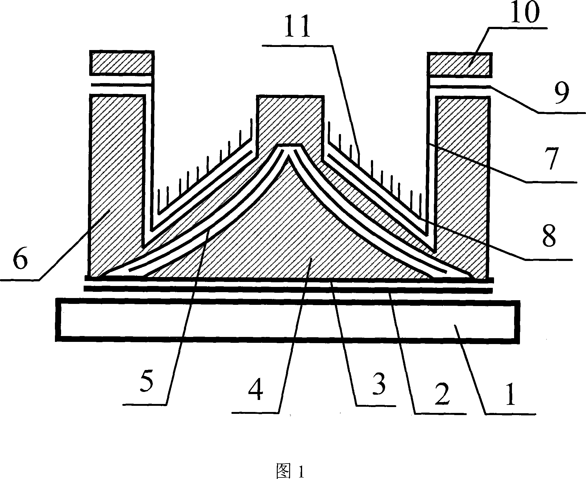
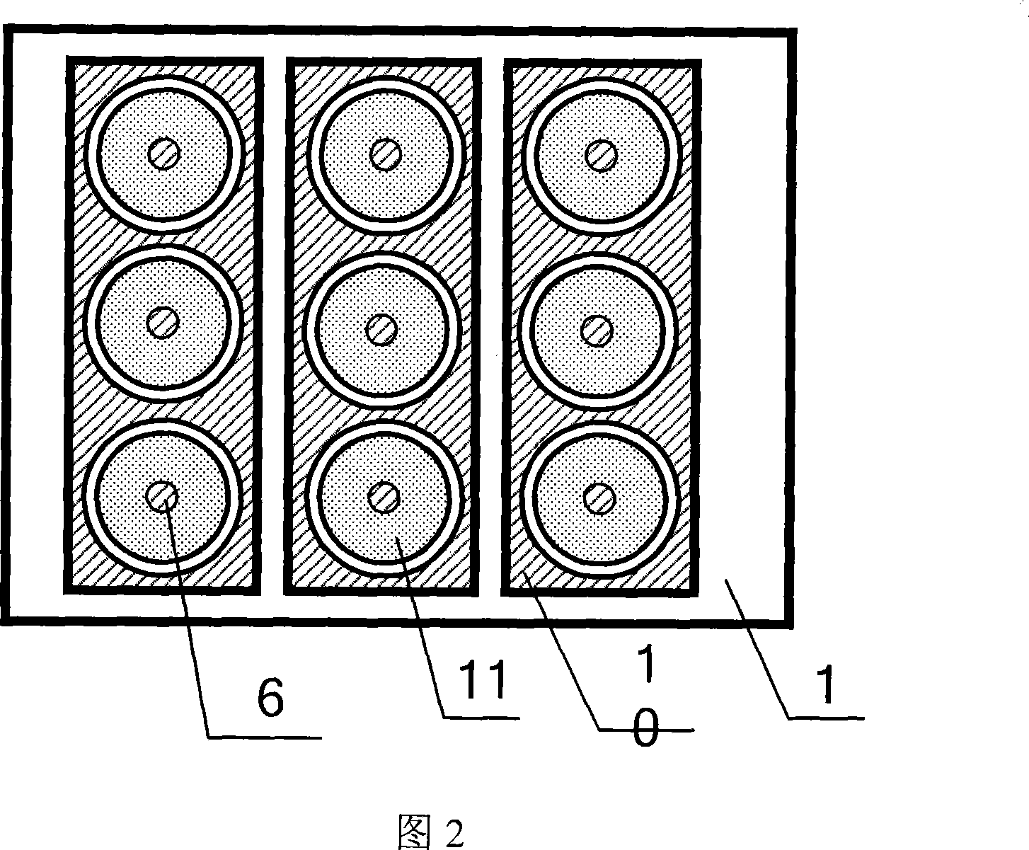
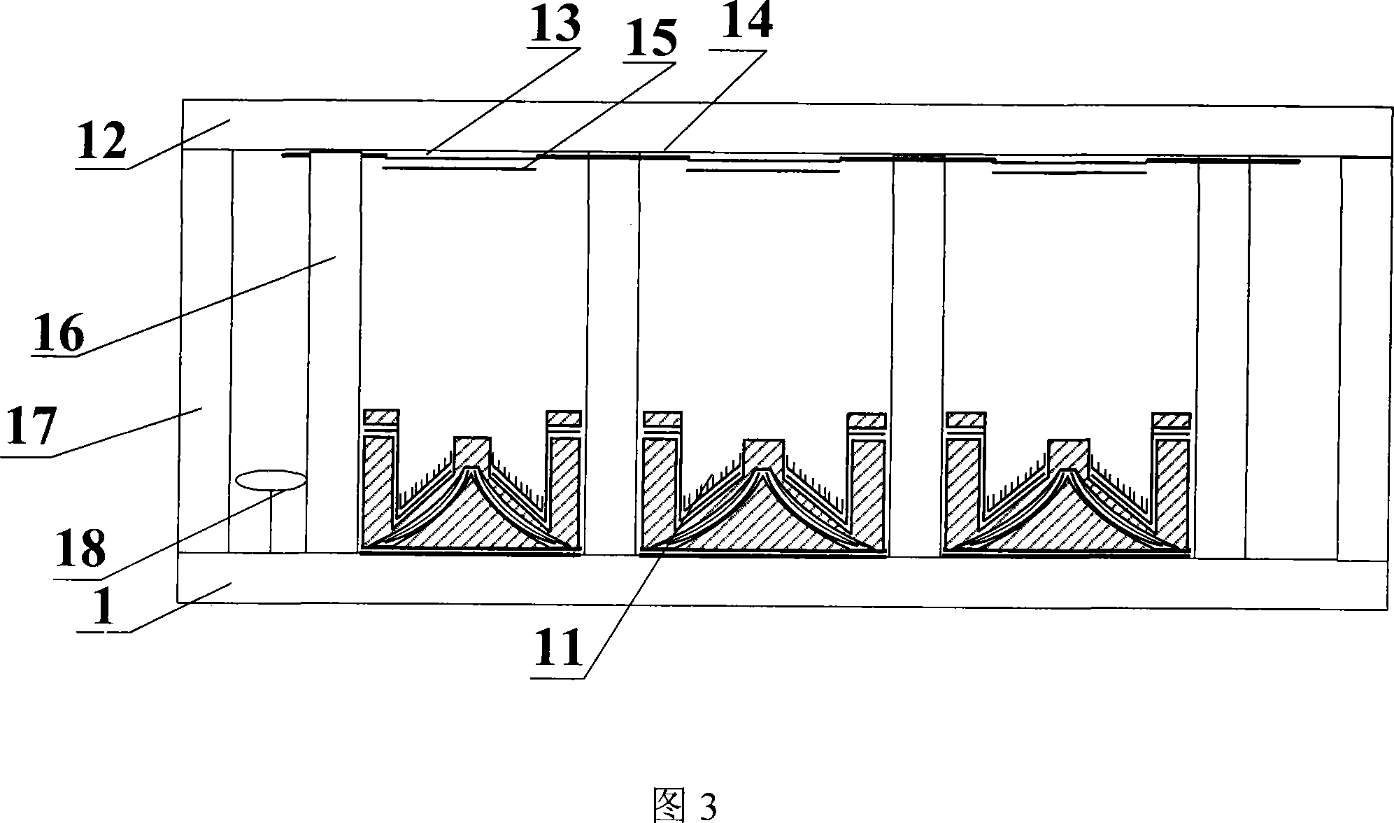
[0039] The flat panel display with grid-controlled curved cathode structure in a concave surface comprises a sealed vacuum chamber composed of an anode glass panel [12], a cathode glass panel [1] and surrounding glass frames [17]; Anode conductive layer on the glass panel [13] and phosphor layer prepared on top of the anode conductive layer [15]; support wall structure between the anode glass panel and the cathode glass panel [16] and getter accessory elements [18] ; A grid lead layer [3], carbon nanotubes [11] and a grid-controlled curved cathode structure within the concave surface are arranged on the cathode glass panel.

[0040] The concave internal gate-controlled curved cathode structure includes a cathode glass panel [1], an insulating layer [2], a grid lead layer [3], a lifting layer [4], a grid control layer [5], and a sp...


PUM


Abstract

This is a flat displayer of concave surface inner side grid cathode structure and its production process. It includes a sealed vacuum chamber formed by a anodic glass panel, a cathode glass panel and surrounded glass frame; on the anodic glass panel is a conducting layer coated with fluorescent; a supporting wall between the anodic and cathode panel and a getter; on the cathode glass panel are a grid down-lead layer, carbon nanotube and concave surface inner side grid structure, which is capable of increasing the display quality.

Description

technical field [0001] The invention belongs to the fields of flat panel display technology, microelectronic science and technology, vacuum science and technology, and nano science and technology, and relates to device fabrication of flat panel field emission displays, in particular to carbon nanotube cathodes. The device manufacturing aspect of the flat panel field emission display particularly relates to a flat panel display with a grid-controlled curved cathode structure inside the concave surface and its manufacturing process. Background technique [0002] As a terminal device that directly displays information, display devices will continue to develop in the direction of high brightness, high resolution, large screen size, large information volume, complete flat panelization, and integration. The working principle of the carbon nanotube cathode field emission display is similar to that of the traditional cathode ray tube display. Carbon nanotubes are used as the cold ca...

Claims


Application Information

Patent Timeline
Patent Type & Authority Applications(China)
IPC IPC(8): H01J31/12H01J31/15H01J29/02H01J29/04H01J1/304H01J9/02H01J9/00
Inventor 李玉魁
Owner ZHONGYUAN ENGINEERING COLLEGE
Why Eureka
Try Eureka