Multiple layer facing machine

A veneer machine and frame technology, applied in the direction of mechanical processing/deformation, can solve problems affecting normal operation, lower production efficiency, difficult debugging and maintenance, etc., to achieve easy debugging and maintenance, high production efficiency, and lamination accuracy Good results

Inactive Publication Date: 2007-11-28
BEIJING INSTITUTE OF GRAPHIC COMMUNICATION
View PDF0 Cites 9 Cited by
  • Summary
  • Abstract
  • Description
  • Claims
  • Application Information

AI Technical Summary

Problems solved by technology

The gluing part of this kind of veneer machine is a single-sided gluing structure, which is mainly composed of an upper rubber roller and a lower water roller that are opposite to each other and rotate synchronously in reverse. The upper rubber roller is equipped with a corresponding glue roller. Therefore, the upper surface of the backing paper can only be glued on one side, and only three layers of corrugated cardboard can be p

Method used


Image

  • Multiple layer facing machine
  • Multiple layer facing machine

Examples


Embodiment Construction

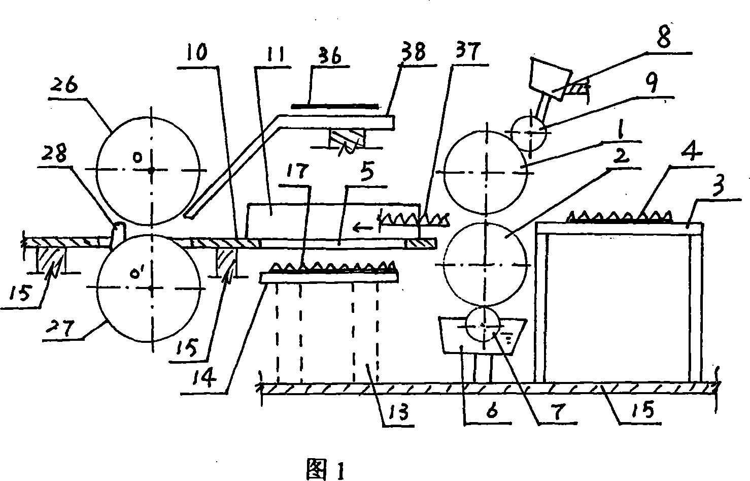
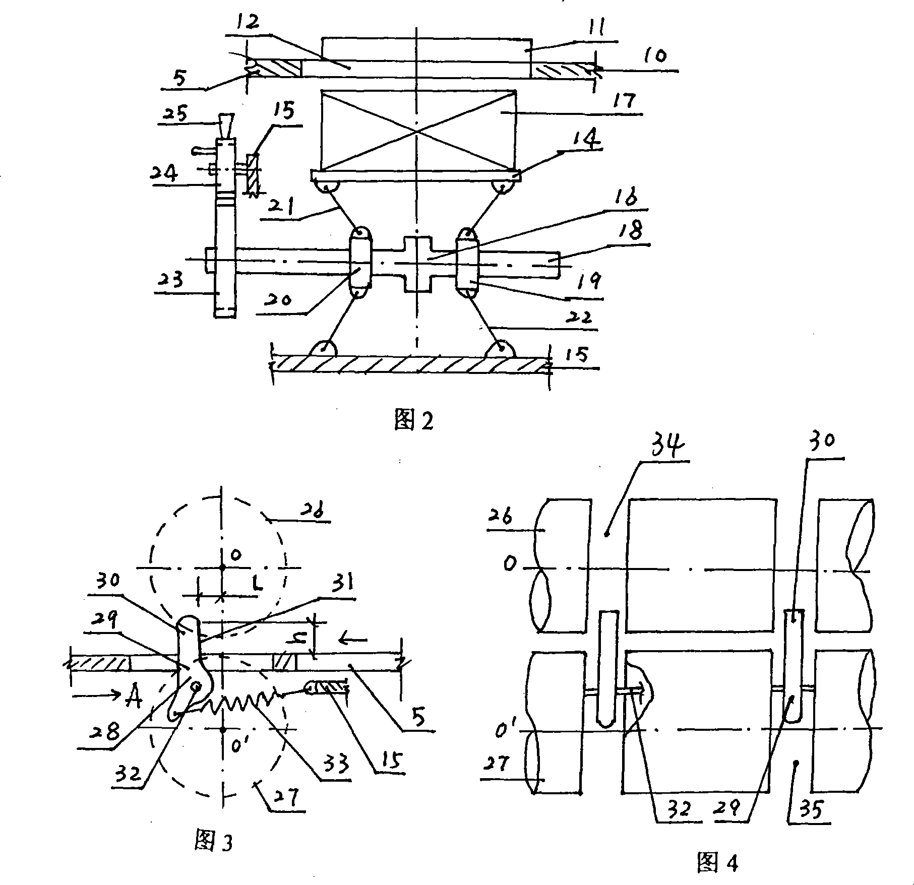
[0013] Further explain in detail in conjunction with accompanying drawings;

[0014] The arrow above the gummed paper bridge 5 in Figures 1 and 3 shows the direction in which the backing paper advances;

[0015] As shown in Figure 1, the upper glue roller 1 and the lower glue roller 2 are opposite to each other and rotate synchronously and reversely, so that the upper bottom paper 4 conveyed from the bottom paper table 3 can be glued on both sides and then transported to the glued paper On the bridge 5; the glue leveling device is as follows, with a glue box 6, a matching lower rubber roller 7 in the box, the rubber roller is associated with the lower rubber roller 2, and the glue is glued by the lower rubber roller 7. The glue in the liquid tank 6 is automatically evenly distributed to the lower rubber roller 2; it also has an upper rubber roller 9 that automatically distributes the glue sent by the glue supply device 8 to the upper rubber roller 1; the glue tank 6 , the low...


PUM


Abstract

The multilayer adhering machine as one kind of light industrial equipment is used for spreading glue to double sides of the base paper to produce five layer corrugated board in once production process. The glue spreading apparatus has one double side spreading structure, and has one upper glue spreading roller and one lower glue spreading roller with separate glue homogenizers, one glued paper bridging device with bottom paper feeding elevator, and one improved pressing device. The present invention is used in spreading glue to double sides of the base paper to produce five layer corrugated board in once production process, and has high reliability, high production efficiency, high adhesion quality, simple structure and easy regulation and maintenance.

Description

technical field [0001] The invention belongs to the field of light industrial equipment and relates to a multi-layer veneer machine. Background technique [0002] In the prior art, the laminating machine, also known as the laminating machine, is widely used in the lamination of color printing surface paper and base paper (corrugated paper or board paper). Package. The laminating machine is mainly composed of two parts: gluing and pressing. When feeding the paper, it adopts the method of manual paper feeding. The top paper and the bottom paper are positioned by the side to ensure the paper feeding of the equipment and the lamination accuracy of the top paper and the bottom paper; The paper is conveyed on the surface paper table, and then, it waits for the arrival of the bottom paper at the front gauge of the photoelectric control and cam drive of the pressing part and the upper and lower point rollers that are opposite to each other and rotate synchronously in reverse. Conv...

Claims


Application Information

Patent Timeline
IPC IPC(8): B31F1/00B31F5/00
Inventor 张阳李光叶理明扈宇
Owner BEIJING INSTITUTE OF GRAPHIC COMMUNICATION
Why Eureka
Try Eureka