Key system and its detection method

A technology of a key system and a detection method, applied in the electronic field, can solve the problems of high system cost and many hardware resources, and achieve the effect of saving space and reducing system cost.

Inactive Publication Date: 2007-11-28
SICHUAN CHANGHONG ELECTRIC CO LTD
View PDF0 Cites 17 Cited by
  • Summary
  • Abstract
  • Description
  • Claims
  • Application Information

AI Technical Summary

Problems solved by technology

[0003] The technical problem to be solved by the present invention is to provide a key system and its detection method for the problems that the existing matrix key scanning circuit occupies many hardware resources and the system cost is high

Method used


Image

  • Key system and its detection method
  • Key system and its detection method
  • Key system and its detection method

Examples


Embodiment 1

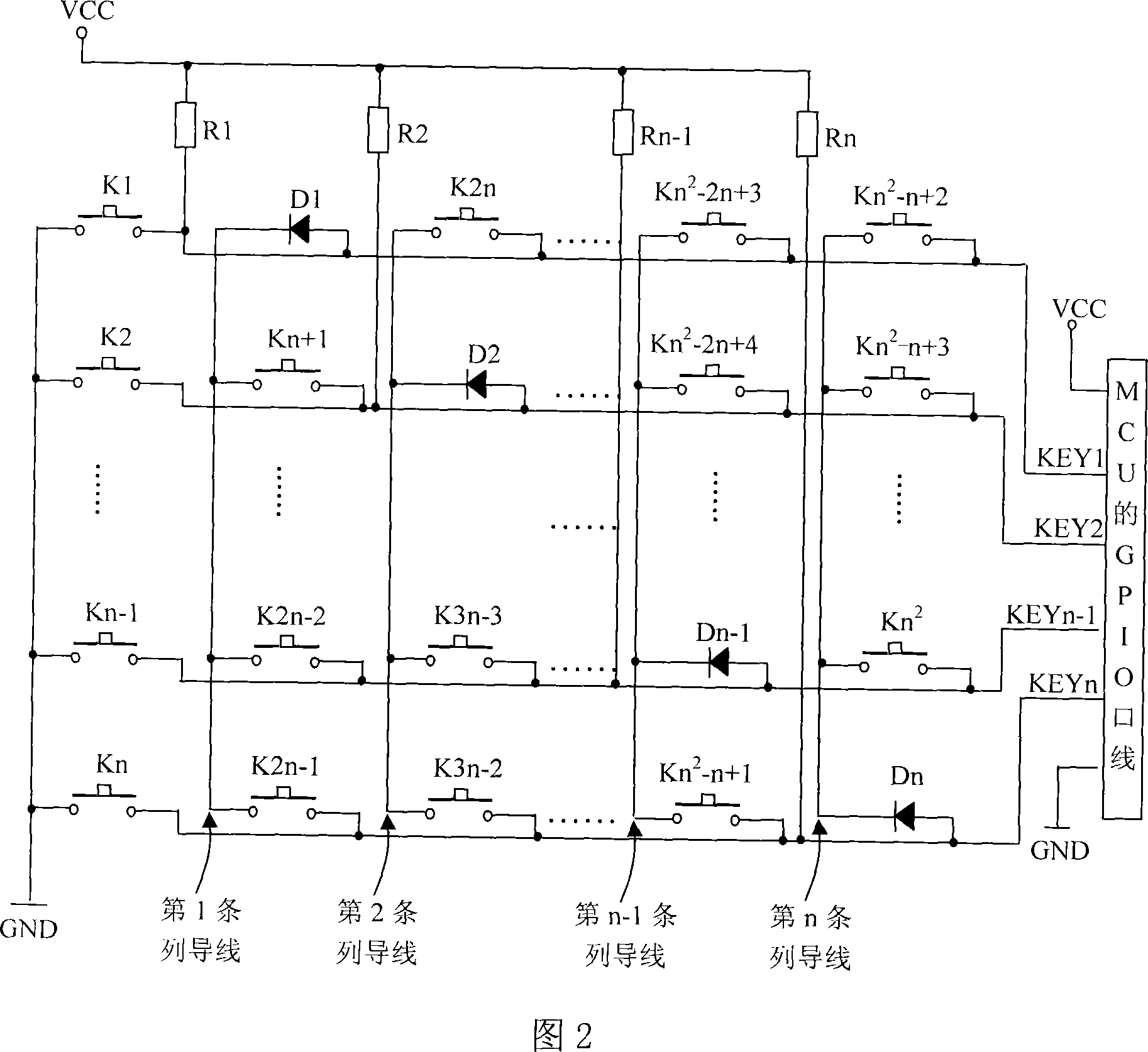
[0050] The button circuit diagram is shown in Figure 4: KEY1~KEY4 represent 4 GPIO ports, D1~D4 represent 4 diodes, K1~K16 represent 16 keys, R1~R4 represent 4 resistors; 4 row wires Connect to the power supply through resistors (D1~D4) respectively; one end of the 4 row wires is grounded through the key (K1~K4), and the other end is respectively connected to the GPIO port line (KEY1~KEY4) of the MCU; 4 row wires and 4 column wires Distributed in a 4×4 matrix to form 4 2 4 intersection points, 4 diodes (D1~D4) are distributed on 4 intersection points on the diagonal line of 4×4 matrix, the anode of the diode is connected to the row wire, and the cathode is connected to the column wire; the remaining 4 2 Buttons (K5-K16) are distributed on the 4 intersection points. When the button is pressed, the row wires and column wires are connected.


PUM


Abstract

The invention discloses a button system and scanning detecting technique of button system, which comprises the following parts: button coding integrated circuit, n strips of line wire, m strips of row wire, m diode, wherein n is not less than m more than 1; n strips of line wire and m strips of row wire are distributed at nXm matrix distribution; n strips of line wire connects the button coding integrated circuit; m strips of row wire connects line wire through diode; the buttons are distributed at residual points of nXm matrix; the line wire and row wire interconnect when pressing the button. The invention saves the space of printed circuit board and entire machine, which reduces the cost of the system.

Description

technical field [0001] The invention relates to electronic technology, in particular to the scanning detection technology of keys. Background technique [0002] At present, most of the products that need to use keys such as disc players, satellite receivers, remote controls, etc. produced by various manufacturers use matrix scanning circuits to connect to the MCU (key coding integrated circuit) for key scanning detection to confirm the state of a certain key; Please refer to Figure 1 for the key scanning method, which involves a key scanning circuit for 4×4 keys, where S15~S0 represent buttons, PA3~PA0 are the input terminals of the row wires, which are initialized as input ports with pull-up resistors, and PA7 ~ PA4 is the output terminal of the column wire, and it is initialized to output low level. Scanning method: first, the output port PA7~PA4 outputs low level to all column wires, and reads the state of each row wire PA3~PA0. If there is a low level in the state, it ...

Claims


Application Information

Patent Timeline
Patent Type & Authority Applications(China)
IPC IPC(8): H03M11/20
Inventor 付强
Owner SICHUAN CHANGHONG ELECTRIC CO LTD
Why Eureka
Try Eureka