
Friction-spring three-dimensional compounded shock isolating pedestal

A seismic isolation bearing and three-dimensional composite technology, which is applied in the direction of building types, buildings, protected buildings/shelters, etc., can solve the problems of poor vertical pull-out resistance, small self-damping, height increase, etc., to ensure work Safety, guaranteed return ability, effect of overall height reduction

Inactive Publication Date: 2007-12-12
BEIJING UNIV OF TECH
View PDF0 Cites 33 Cited by
  • Summary
  • Abstract
  • Description
  • Claims
  • Application Information

AI Technical Summary

Problems solved by technology

Although the laminated rubber bearing can prolong the natural vibration period of the structure, due to its own physical characteristics, it has the following defects: it can only isolate the horizontal earthquake action, and cannot achieve multi-dimensional isolation; its own damping is small, resulting in the structure in the earthquake There will be a large horizontal displacement under the action; the vertical pull-out resistance is poor; the self-resetting ability after the earthquake is insufficient
The above system is feasible in multi-storey structures, but there are the following problems in applying it to large-span grid roof structures: (1) The horizontal seismic isolation support is connected in series with the vertical seismic isolation device, so that the height of the support Under the action of the eccentric additional bending moment of the support, it is difficult to ensure the stability of the support; (2) the rubber support is used for horizontal isolation. Due to the small horizontal damping, the horizontal displacement of the structure under the earthquake Larger; (3) Lack of vertical pull-out resistance and lack of bearing rotation capacity

Method used


Image

  • Friction-spring three-dimensional compounded shock isolating pedestal
  • Friction-spring three-dimensional compounded shock isolating pedestal
  • Friction-spring three-dimensional compounded shock isolating pedestal

Examples


Embodiment Construction

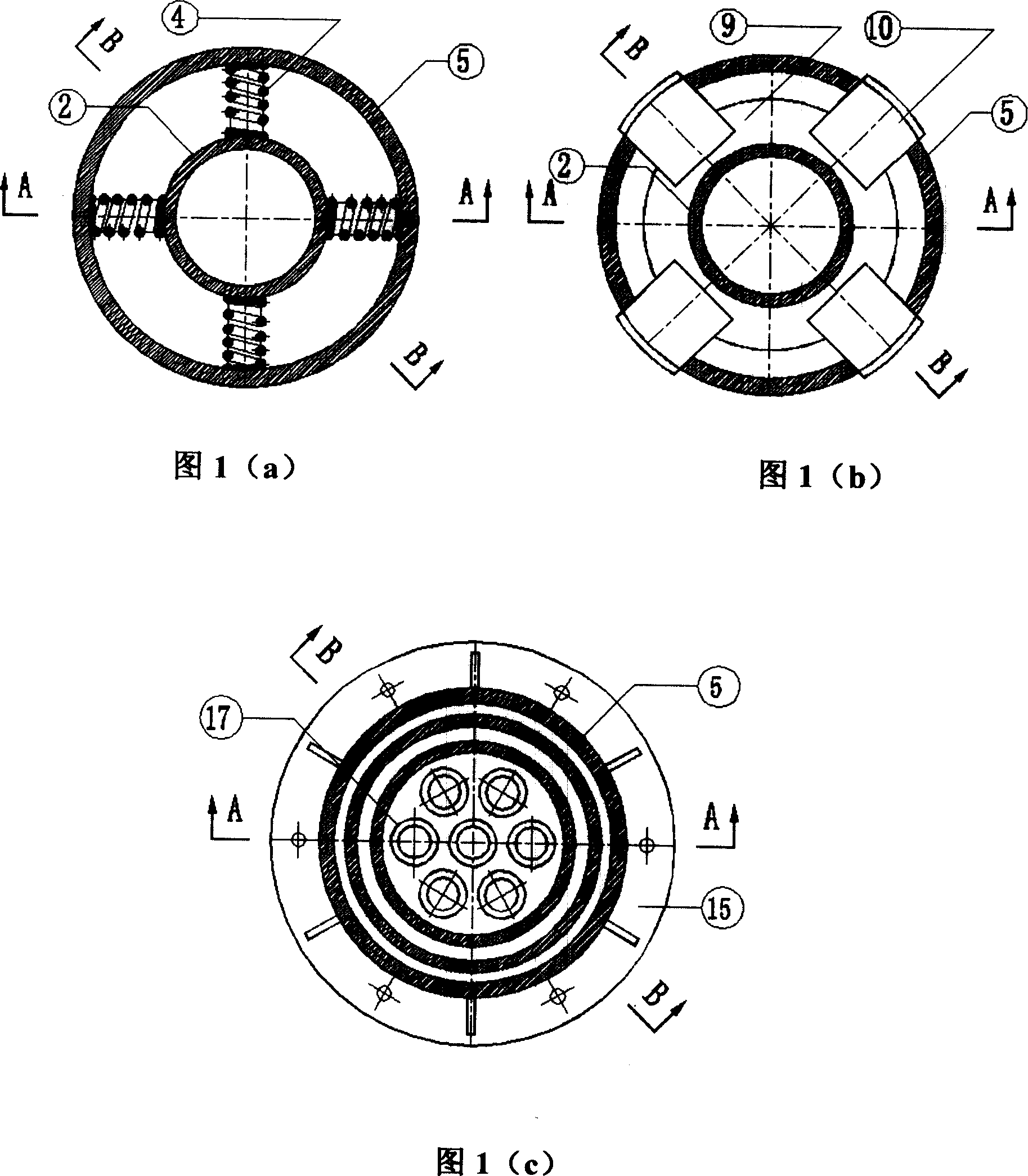
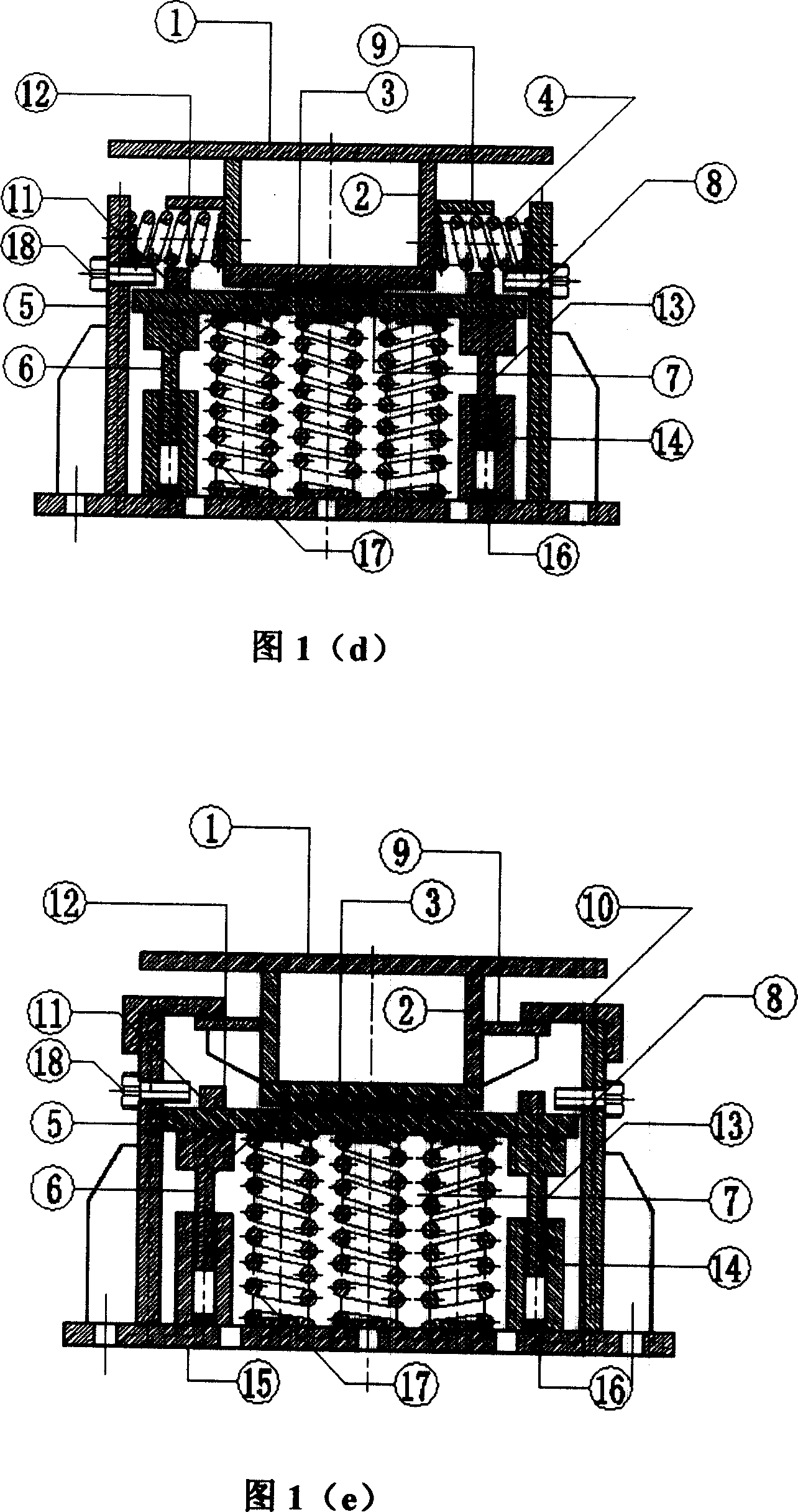
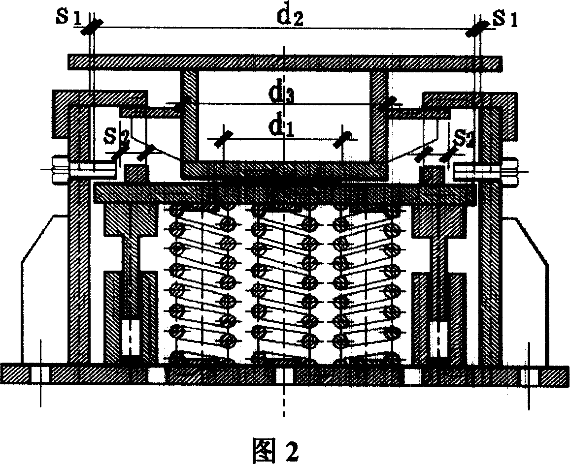
[0026] The implementation basis of the present invention is Fig. 1, can process according to six main components according to the support structure and assembly procedure. Part I is composed of the outer casing 5 fixed on the bottom connecting plate 15 and the guide tube 14. Part II is a vibration isolation spring 17. Part III includes a vertical spring pressure plate 8 and a sliding cylinder 13. The sliding cylinder 13 is fixed on On the lower surface of the vertical spring pressure plate 8, part IV is a vertical spring limiter, part V is a horizontal supporting member, a horizontal return spring 4 and a limit plate 9, and part VI is a limit baffle 10. First of all, the main components are processed, and then assembled. The assembly sequence is from bottom to top. The main steps can be summarized as follows:

[0027] (1) Install a vertical vibration isolation spring in part I;

[0028] (2) Installation part II;

[0029] (3) Installation part III;

[0030] (4) Apply vertica...


PUM


Abstract

The friction spring three-dimensional composite shock-proof bearing belongs to the shock insulation and damping control area. The application of the prior three-dimensional composite shock-proof bearing into the large span mesh roof structure has the following problems: (1) the level shock-proof bearing is series-connected with the vertical shock-proof device, the height of the bearing is large, so it is lack of stability ; (2) the horizontal displacement of the structure under earthquake is large, (3) it is lack of vertical pulling-proof ability, the bearing rotational capacity is insufficient. The composite shock-proof bearing in the invention mainly includes horizontal shock-proof device and vertical shock-proof device, the whole appearance of bearing is cylindrical. The horizontal direction of the bearing uses the plate slip shock-proof device to lower the height of bearing, and the stability is effectively guaranteed, at the same time the horizontal direction also is equipped with reset and spacing device to make the bearing has reset and spacing functions. The vertical direction uses spring shock-proof and has rational rotary capability through the structure design. In addition, the integral bearing in the invention has the anti-pulling performance.

Description

technical field [0001] The invention relates to a support with horizontal and vertical three-dimensional compound shock isolation functions, which belongs to the field of shock isolation and shock absorption control of building structures. Background technique [0002] The passive control technology of the support isolation system is to reduce the seismic response of the upper structure by setting an isolation device between the upper structure and the lower support system. The excellent period is staggered, so as to avoid the structural vibration of the part of the structure that is close to the excellent period of the earthquake action, and at the same time reduce the energy input of the earthquake motion to the structure, thereby reducing the seismic response of the structure. [0003] With the rapid development of my country's social economy, the space grid structure has been widely used in gymnasiums, exhibition halls, convention centers, terminal buildings and industri...

Claims


Application Information

Patent Timeline
IPC IPC(8): E04H9/02
Inventor 薛素铎李雄彦
Owner BEIJING UNIV OF TECH
Learn More