Monitoring system of optical fiber remote multi-point switch status

A state monitoring system and multi-point switch technology, applied in the field of sensing monitoring, can solve the problems of fragile installation methods, inapplicability, and the switch monitoring system cannot meet the detection requirements, and achieve the effects of precise positioning and stable and reliable performance.

Inactive Publication Date: 2007-12-12
上海光子光电传感设备有限公司
View PDF5 Cites 7 Cited by
  • Summary
  • Abstract
  • Description
  • Claims
  • Application Information

AI Technical Summary

Problems solved by technology

[0002] Due to the diversification of monitoring environments and requirements, higher and higher requirements are placed on the performance and adaptability of sensors. The traditional switch monitoring system can no longer meet the stringent detection requirements.
For example, the monitoring systems mentioned in patents 200310105802.0 and 02238116.3 are not suitable for high-voltage, flammable and other environmental conditions due to the use of electric excitation. If there is no power supply on site or electricity is prohibited, then these products will be useless
[0003] The latest optical fiber sensor, patent No. 200510025483.1, although it solves the problem of working in a high-voltage environment, still has the following disadvantages: single-point sensing, when there are many measured objects or scattered distribution, a single system appears to be Powerless; the sensing method is contact, has mechanical friction, is easy to damage and has limitations in installation; the sensor structure is complex and difficult to popularize; photoelectric converters are required to convert optical signals into electrical signals, which is not suitable for long-distance monitoring
[0004] Although the invention patents with patent numbers 89107596.8 and 92115028.8 have realized long-distance multi-point monitoring, the fatal disadvantage is that these systems require on-site power supply
In recent years, fiber grating monitoring technology, which is more popular in recent years, has limited its development in this field due to its high cost, contact sensing, high possibility of abnormal failure, and limited number of sensors connected in series.

Method used


Image

  • Monitoring system of optical fiber remote multi-point switch status
  • Monitoring system of optical fiber remote multi-point switch status

Examples


Embodiment Construction

[0021] Further illustrate the present invention below in conjunction with accompanying drawing.

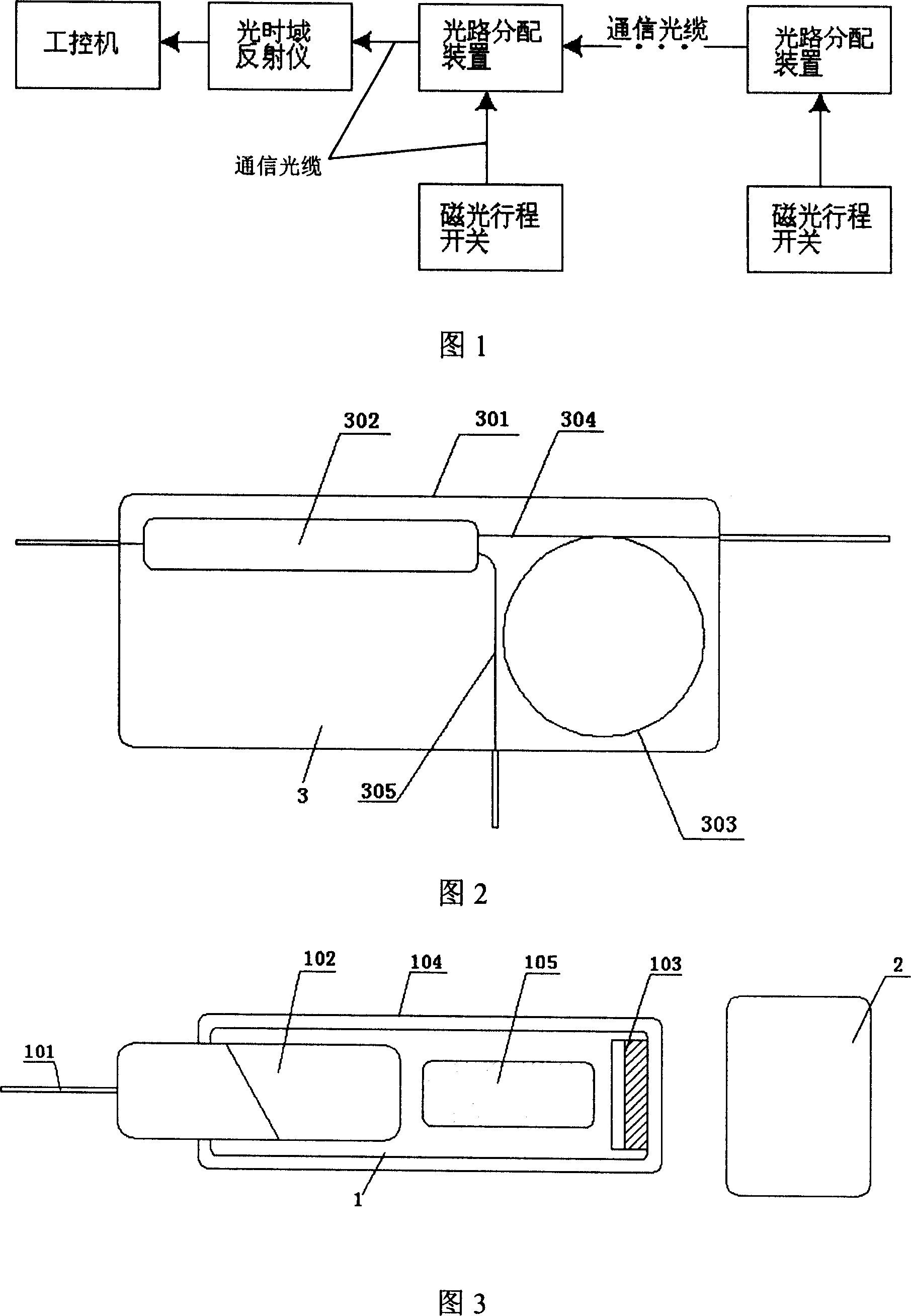
[0022] As shown in the principle diagram of the monitoring system of the present invention in Figure 1, the optical fiber remote multi-point switch state monitoring system of the present invention includes an industrial computer, an optical time domain reflectometer, an optical path distribution device and a magneto-optical travel switch connected to each other in sequence;

[0023] There are multiple optical path distribution devices, which respectively include an input end and two output ends, one output end of the optical path distribution device is connected to the input end of the magneto-optical travel switch, and the other output end of the optical branching device is connected to the latter The input ends of the optical path distribution device are connected, and a plurality of magneto-optical travel switches are connected in parallel through the optical path distribution d...


PUM


Abstract

The invention belongs to fields of sensing technique monitoring. It discloses an optical fibre remote multi-point switch state monitoring system. It includes industry controller, optic time domain reflector, optical path distributing device and magneto optical journey switch; it possesses several the optical path distributing devices, it separately includes one input and two outputs, one output of the optical path distributing device is connected with input of magneto optical journey switch, the another output of the optical path distributing device is connected with input of later optical path distributing device, several magneto optical journey switches are connected parallel via optical path distributing device, adjacent optical path distributing device, the optical path distributing device and magneto optical journey switch, and adjacent optical path distributing device are connected via communication cable. The invention is insulated, safe, locale dues not need electricity, it adopts non-contact magneto optical journey switch, and structure is easy, can fit for high-voltage, high-powder, and damp circumstance.

Description

technical field [0001] The invention belongs to the technical field of sensor monitoring, and relates to a switch state monitoring system, in particular to a remote multi-point switch state on-line monitoring system suitable for working in harsh environments such as high voltage, flammable, and no power supply on site. Background technique [0002] Due to the diversification of monitoring environment and needs, the performance and adaptability of sensors are increasingly required, and the traditional switch monitoring system can no longer meet the stringent detection requirements. For example, the monitoring systems mentioned in patents 200310105802.0 and 02238116.3 are not suitable for high-voltage, flammable and other environmental conditions due to the use of electric excitation. If there is no power supply on site or electricity is prohibited, then these products will be useless . [0003] The latest optical fiber sensor, patent No. 200510025483.1, although it solves th...

Claims


Application Information

Patent Timeline
Patent Type & Authority Applications(China)
IPC IPC(8): H03K17/968
Inventor 林麟葛捷宁娜
Owner 上海光子光电传感设备有限公司
Why Eureka
Try Eureka