
Cold mat system for protecting buried object in permafrost area, and construction method of cold mat system

A technology for permafrost areas and objects, applied in soil protection, pipeline protection, pipeline protection through thermal insulation, etc., can solve problems such as uneven settlement, difficulty in permafrost foundation stability, and inability to reach, to overcome differential freezing. Expansion, melting and sinking, continuous and uniform temperature control effect, and overall temperature control effect

Pending Publication Date: 2019-07-12
COLD & ARID REGIONS ENVIRONMENTAL & ENG RES INST CHINESE
View PDF4 Cites 0 Cited by
  • Summary
  • Abstract
  • Description
  • Claims
  • Application Information

AI Technical Summary

Problems solved by technology

However, the measures in the prior art still fail to effectively deal with the stability of linear engineering foundations in permafrost regions, for example, the following problems still exist:
[0007] (1) In fact, all linear projects in permafrost regions have the problem of uneven settlement, especially for buried oil (gas) pipeline projects, in order to avoid severe frost heaving or thawing settlement, interval support, or Heat pipes are inserted at intervals on both sides of the pipeline, and the heat pipe is characterized by point cooling, that is, the cooling effect is remarkable at the position where the heat pipe is inserted, and the frost heaving and thawing of the soil in the pipe section with measures is relatively moderate, while the soil in the pipe section without heat pipe measures Freezing and thawing is still relatively strong, and this differential settlement leads to more common and serious deformation and warping of the entire pipeline, which seriously affects the stability of the project
[0008] (2) Although the geotechnical engineering, pipeline materials and construction technology in the permafrost area are changing with each passing day, the foundation instability caused by the permafrost melting around the pipeline caused by the heat carried by itself and the heat generated by friction during oil / gas transportation The problem has not been well resolved so far, and the application of corresponding technical inventions is still blank
[0009] (3) Although there are currently a large number of patents (inventions, utility models) named "cold pad" or "refrigeration system", such as: a slow-release constant temperature cold pad (application number: 201420231993.9), non-powered heat preservation or Cold insulation pad (application number: 201420421925.9), refrigeration system (application number: 201680043949.7), a refrigeration system (application number: 201711266214.3), etc., but these technologies all require special power supply, and in remote areas, especially in remote areas In permafrost areas, electricity is scarce or cannot be delivered, and technologies that rely on electricity for cooling cannot be promoted and implemented
For engineering construction in the vast alpine permafrost region, maintaining the stability of the permafrost foundation is the most important thing to ensure the safe operation of the project and promote regional economic development. Existing refrigeration and heat preservation measures are difficult to ensure large-scale, especially long-distance linear engineering permafrost The problem of stable foundation

Method used


Image

  • Cold mat system for protecting buried object in permafrost area, and construction method of cold mat system
  • Cold mat system for protecting buried object in permafrost area, and construction method of cold mat system
  • Cold mat system for protecting buried object in permafrost area, and construction method of cold mat system

Examples


Embodiment Construction

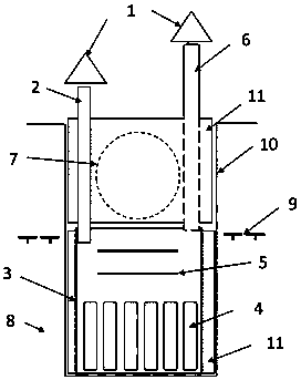
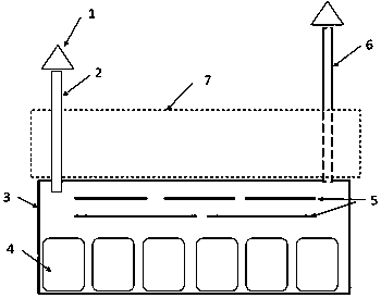
[0038] refer to Figure 1~2 , the embodiment of the present invention discloses a cold pad system for protecting buried objects in permafrost regions. The air outlet channel 6, the bottom of the internal space of the energy storage cooling box 3 is provided with an energy storage body 4, and the upper part is provided with a radiation heat shield 5 placed horizontally, the air inlet channel 2 and the air outlet channel 6 are in the energy storage cooling box 3 The top is arranged diagonally to ensure that the air inside the box can participate in the convective heat transfer process as much as possible.

[0039] The cold pad system may further include a dust cover 1 arranged above the top of the air inlet channel 2 and / or the air outlet channel 6 for preventing the entry of external dust, precipitation, sand grains and the like.

[0040] When the cold pad system of the present invention is put into use, the energy storage cooling box 3 is arranged on the frozen soil layer 8, ...


PUM


Abstract

The invention relates to a cold mat system for protecting a buried object in a permafrost area, and a construction method of the cold mat system. The cold mat system comprises an energy storage cooling box, and further comprises an air feeding channel and an air discharging channel which are formed in the top of the box and communicate with the box; the energy storage cooling box is used for beingarranged on a frozen soil layer and placed below the to-be-protected buried object, and the top of the energy storage cooling box is not lower than the frozen soil upper limit; and the air feeding channel and the air discharging channel are located in the two sides of the to-be-protected buried object, and the tops of the air feeding channel and the air discharging channel are both higher than the ground surface and communicate with the natural atmosphere. When the cold mat system is applied, the shape and size of the cold mat system adapt to those of the to-be-protected buried object, the overall and even temperature control effect can be provided for the to-be-protected buried object only through natural resources in the natural environment, thus frozen soil on the periphery of the to-be-protected buried object is always in a stable low-temperature state, the phenomena of frost heaving in the cold season and thaw collapse in the warm season are effectively prevented, and the problems of differential frost heaving and thaw collapse of the buried object in the frozen soil area, especially in linear engineering are fundamentally solved.

Description

technical field [0001] The invention relates to the technical field of cold pads in permafrost regions, in particular to a cold pad system for protecting buried objects in permafrost regions and a construction method thereof. Background technique [0002] The mechanical strength of frozen soil will change greatly with the change of temperature: the lower the temperature, the greater its strength. When the temperature is lower than -1.5°C, its instantaneous compressive strength is equivalent to that of ordinary rocks; while the temperature is higher than -0.5°C At 0°C, its compressive strength is equivalent to that of ordinary soil blocks, or even basically lost. [0003] my country's imports of crude oil and natural gas from Russia and Kazakhstan are growing at an unprecedented rate. However, the pipelines for transporting these oil and gas resources must pass through perennial and seasonal permafrost regions, and oil and gas pipeline engineering in permafrost regions is a g...

Claims


Application Information

Patent Timeline
IPC IPC(8): E02D3/11E02D3/115F16L59/02
CPCE02D3/11E02D3/115F16L59/02Y02E60/14
Inventor 俞祁浩王俊峰李国玉
Owner COLD & ARID REGIONS ENVIRONMENTAL & ENG RES INST CHINESE
Learn More