A processing method for multi-node communication failure

A technology for communication faults and processing methods, which is applied to the selection device of multiplexing systems, digital transmission systems, electrical components, etc., and can solve problems such as affecting transport plane services and failing to reliably restore LSPs.

Active Publication Date: 2007-12-12
HUAWEI TECH CO LTD
View PDF0 Cites 20 Cited by
  • Summary
  • Abstract
  • Description
  • Claims
  • Application Information

AI Technical Summary

Problems solved by technology

Therefore, the PSB on node C cannot be restored, and node D will stop the self-refresh processing of PSB after receiving the HELLO message sent by node C after restarting, so the PSB on node D will not receive node C for a long time The sent Path message is timed out and deleted, and after the timer corresponding to its own RSB expires, node D will send a reservation deletion (Resv_Tear) message to node C, informing node D to delete the local RSB, which will cause the corresponding LSP been deleted
[0026] It can be seen that applying the existing node restart processing method, when communication failures occur in multiple nodes on the LSP path, the LSP cannot be reliably restored, so that the failure of the control plane affects the services of the transmission plane

Method used


Image

  • A processing method for multi-node communication failure
  • A processing method for multi-node communication failure
  • A processing method for multi-node communication failure

Examples


Embodiment 1

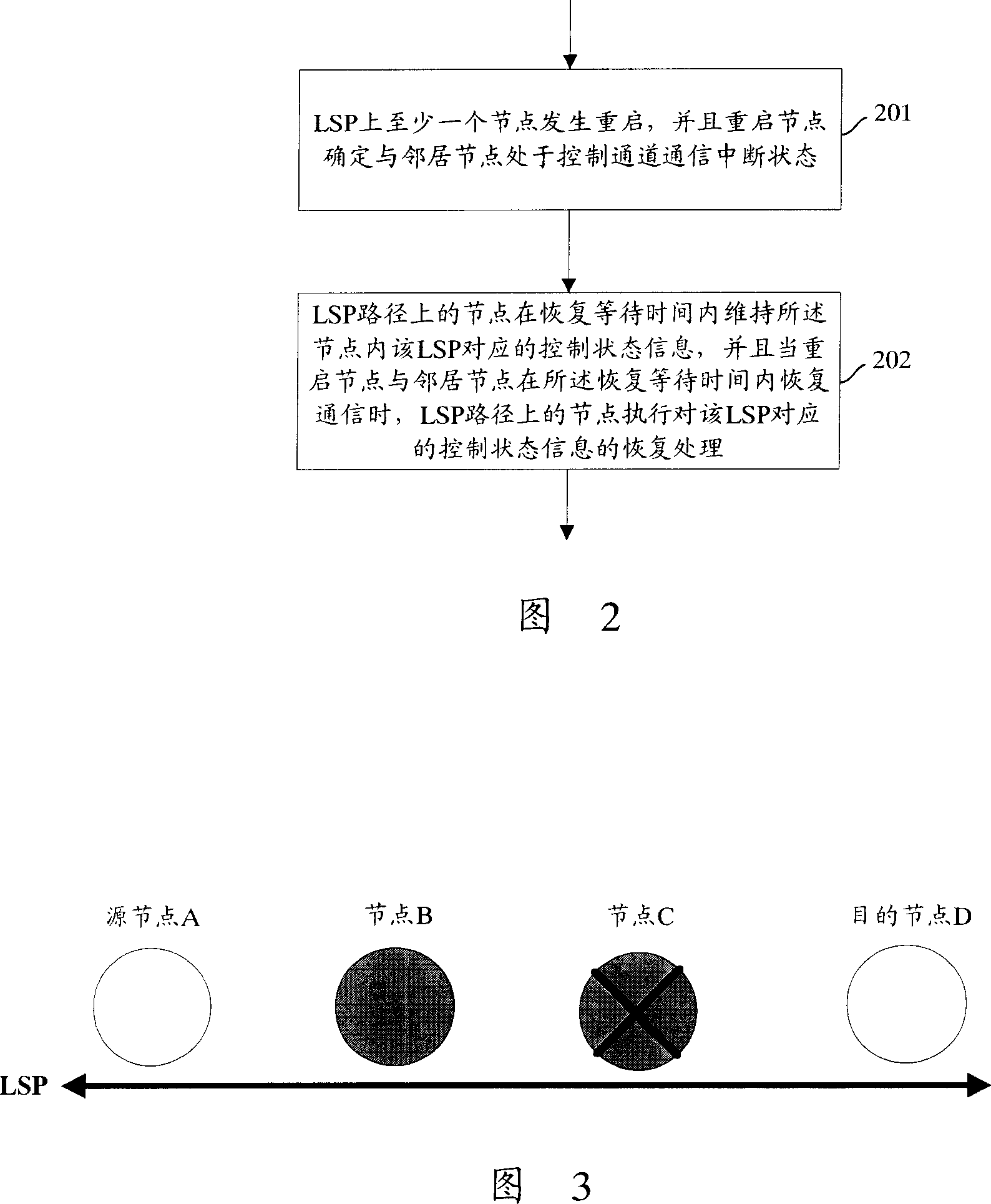
[0102] In this embodiment, an LSP passing through nodes A, B, C, and D in sequence is taken as an example for illustration. Fig. 3 shows a schematic diagram of the running status of nodes on the LSP path in this embodiment. As shown in FIG. 3 , Node B and Node C are powered off, and Node B restarts, and Node C fails to restart for a long time. Node B is the restart node, node C is the neighbor node of node B, node A is the normal node in the upstream direction closest to the restart node B, and node D is the normal node in the downstream direction closest to the restart node B. Here, according to mode 1, the recovery waiting time is set on the normal node closest to the restart node on the LSP path, that is, node A.

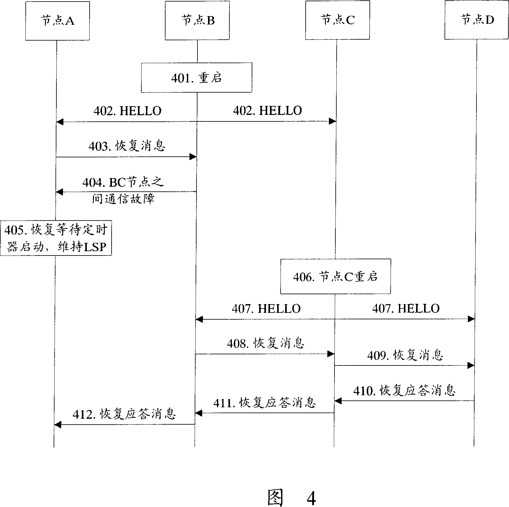
[0103] Fig. 4 shows a flow chart of the multi-node communication fault handling method in this embodiment. Referring to Figure 4, the method includes:

[0104] In steps 401-402, node B is powered on and restarted, sends a HELLO message to node A and node C, an...

Embodiment 2

[0121] In this embodiment, the LSP shown in FIG. 3 is still taken as an example, node B restarts, and node C fails to restart for a long time. Here, according to mode 2, the recovery waiting time is set on the restarting node, that is, node B, and the failure information of communication interruption is sent to node A.

[0122] Fig. 5 shows a flow chart of the multi-node communication fault handling method in this embodiment. Referring to Figure 5, the method includes:

[0123] In steps 501-502, node B is powered on and restarted, sends a HELLO message to node A and node C, and node B learns that node B and node C are in a communication failure state through the HELLO message mechanism.

[0124] Here, in the HELLO message sent by node B, the src-instance value is the value before power failure + 1, and the dst-instance value is 0, so that node A and node C know the restart of node B.

[0125] After node B sends a HELLO message to node C, it does not receive a response from n...

Embodiment 3

[0137] In this embodiment, the LSP shown in FIG. 3 is still taken as an example, node B restarts, and node C fails to restart for a long time. Here, according to mode 3, the recovery waiting time is set on the restarting node, that is, node B, and a normal recovery response message is constructed and sent to node A.

[0138] Fig. 6 shows a flow chart of the multi-node communication fault handling method in this embodiment. Referring to Figure 6, the method includes:

[0139] In steps 601-602, node B is powered on and restarted, sends a HELLO message to node A and node C, and node B learns that node B and node C are in a communication failure state through the HELLO message mechanism.

[0140] After node B sends a HELLO message to node C, it does not receive a response from node C to the HELLO message, so it is determined that the communication between node B and node C is interrupted. The cause of communication interruption between the two nodes may not only be that node C i...


PUM


Abstract

The invention discloses a processing method for multi-node communication failure, and the method includes: A. restarts at least one node on label switch path LSP, and the restarting node determines the control channel in interruptable state of adjacent nodes; B. the node on LSP in waiting time keeps the control state information corresponding with LSP, and when the restarting node and adjacent node recover the communication, the node on LSP path recovers the control state information corresponding with said LSP. Using the invention, it can recover the LSP when several nodes on LSP have communication failure.

Description

technical field [0001] The invention relates to general multi-protocol label switching (GMPLS) technology, in particular to a processing method for multi-node communication faults in GMPLS. Background technique [0002] At present, under the dual drive of the bandwidth demand generated by the rapid growth of Internet Protocol (IP) services and the new bandwidth utilization mode introduced by WDM technology, the suddenness and uncertainty of IP services require the realization of network bandwidth. Dynamic allocation, while the traditional static optical transmission network is difficult to meet the needs of dynamic allocation, so the intelligent optical network came into being. The intelligent optical network directly introduces the intelligent control technology with IP as the core on the optical fiber network, so as to effectively support the dynamic establishment and removal of connections, and reasonably allocate network resources on demand based on traffic engineering, ...

Claims


Application Information

Patent Timeline
IPC IPC(8): H04L12/24H04L12/54
CPCH04L41/0654H04L45/28H04L45/50H04Q11/0062H04Q2011/0081H04Q2011/0088
Inventor 高建华李丹
Owner HUAWEI TECH CO LTD
Why Eureka
Try Eureka