Tracking by cross correlating central apertures of multiple beams

A tracking error, interrelated technique used in head configuration/mounting, optical recording/reproducing, instrumentation, etc.

Inactive Publication Date: 2007-12-12
KONINKLIJKE PHILIPS ELECTRONICS NV
View PDF0 Cites 0 Cited by
  • Summary
  • Abstract
  • Description
  • Claims
  • Application Information

AI Technical Summary

Problems solved by technology

Much worse tracking with push-pull based only on radial diffraction

Method used


Image

  • Tracking by cross correlating central apertures of multiple beams
  • Tracking by cross correlating central apertures of multiple beams
  • Tracking by cross correlating central apertures of multiple beams

Examples


Embodiment Construction

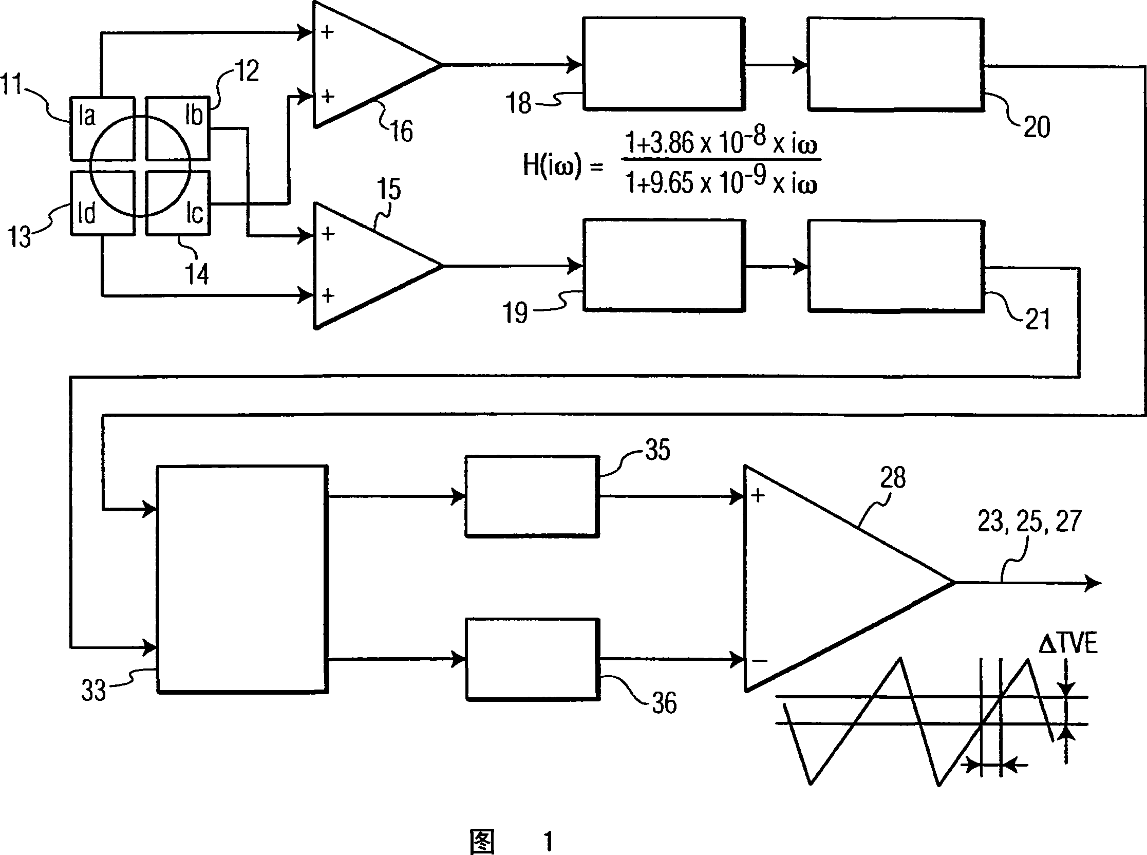
[0020] Referring to FIG. 1 , there is shown a block diagram of differential phase detection (DPD) used in the prior art for detecting light that has been reflected from an optical disc by a single spot. Differential phase detection has been used in the prior art to generate tracking error (TE) signals. Using the DPD shown in FIG. 1 , the TE is generated by difference in phase of the signals received in the diagonal light receiving parts of the four divided photodetectors 11 , 12 , 13 , 14 . The signals received by the photodetectors 11, 12, 13, 14 are fed into amplifiers 15, 16 and arranged so that the tangential diffraction can be determined from the difference between the upper two and the lower two detector quadrants, And radial diffraction can be determined by the difference between the left two and right two detector quadrants. This process using DPD is well known in the art. As shown in FIG. 1, equalizers 18, 19, level comparators 20, 21, phase comparator 33, low pass ...


PUM


Abstract

The present invention provides a method and apparatus for robust tracking at narrow track-pitches on optical discs, enabling higher densities on Blu-ray Discs (5) as well as near-field discs. Increasing radial density results in loss of radial diffraction within the numerical aperture of the lens. Due to this loss in diffraction, current tracking methods, such as Push-Pull and Differential Phase Detection (DPD), will stop working. The invention provides a method and apparatus that relies on cross-correlating the central aperture (CA) signals of 3 optical spots (22, 24, 26) that are positioned such that there are a central spot (24) and spots (22, 26) positioned to the left (22) and right (26) of the central spot (4). By using CA signals, the tangential diffraction is used, which is hardly affected by a track-pitch reduction.

Description

technical field [0001] This invention relates to tracking optical discs, and more particularly to preserving tracking error signals in optical discs with very small track pitches. Background technique [0002] Optical disc storage systems generally adopt run-length limited (RLL) modulation codes used in optical disc storage systems to improve transmission performance according to optical channel characteristics. A run is defined as a continuous sequence of bits (0 or 1) of the same type recorded on the disc. The length is the number of bits in the sequence. For example, the binary bit sequence 00100 is illegal, while the binary sequence 001100 is legal. In the Blu-ray Disc format, the shortest sequence is of length 2, referred to as I2, and the longest sequence is of length 9, referred to as I9. It should be noted that I8 is the longest run length of data and the maximum run length I9 is ​​only used for frame synchronization to indicate the start and end of a data frame. ...

Claims


Application Information

Patent Timeline
Patent Type & Authority Applications(China)
IPC IPC(8): G11B7/09
CPCG11B7/0903G11B7/0943G11B7/09
Inventor R·夫卢特斯B·尹
Owner KONINKLIJKE PHILIPS ELECTRONICS NV
Why Eureka
Try Eureka