Built-in refuse incineration feed device

A waste incineration and feeding device technology, which is applied in the direction of incinerators, combustion methods, combustion types, etc., can solve the problems of reducing feeding efficiency, increasing the load of push carts, and energy waste, so as to improve feeding efficiency and avoid energy consumption. Waste and eliminate the effect of pushing material dead zone

Inactive Publication Date: 2007-12-19
CHONGQING UNIVERSITY OF SCIENCE AND TECHNOLOGY
View PDF0 Cites 5 Cited by
  • Summary
  • Abstract
  • Description
  • Claims
  • Application Information

AI Technical Summary

Problems solved by technology

[0003] When the push cart moves backward, the garbage in the silo continuously falls to the upper surface of the upper and lower car bodies and the upper surface of the fixed chassis; when the push cart moves forward, the front end surfaces of the upper and lower car bodies and the The sliding block pushes the garbage forward, so that the garbage on the

Method used


Image

  • Built-in refuse incineration feed device
  • Built-in refuse incineration feed device

Examples


Embodiment Construction

[0013] Below in conjunction with accompanying drawing and embodiment the present invention will be further described:

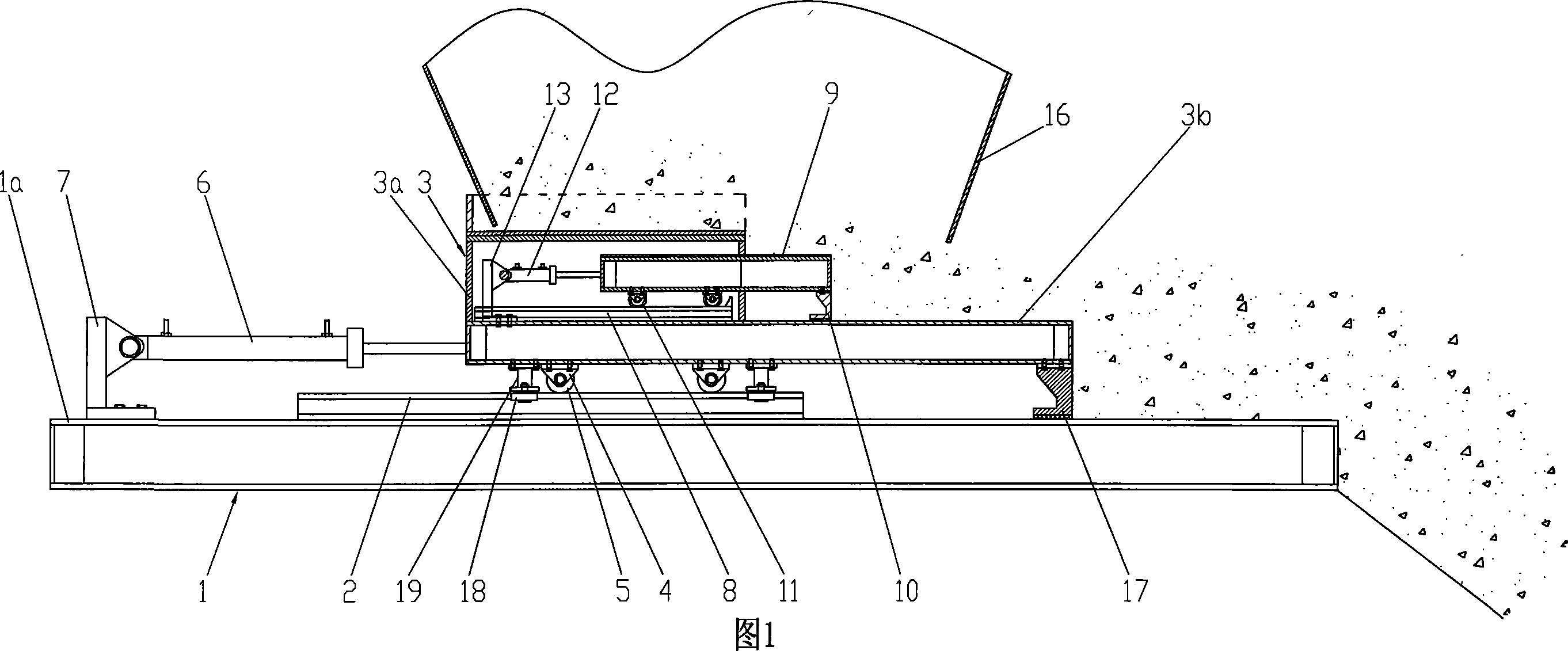
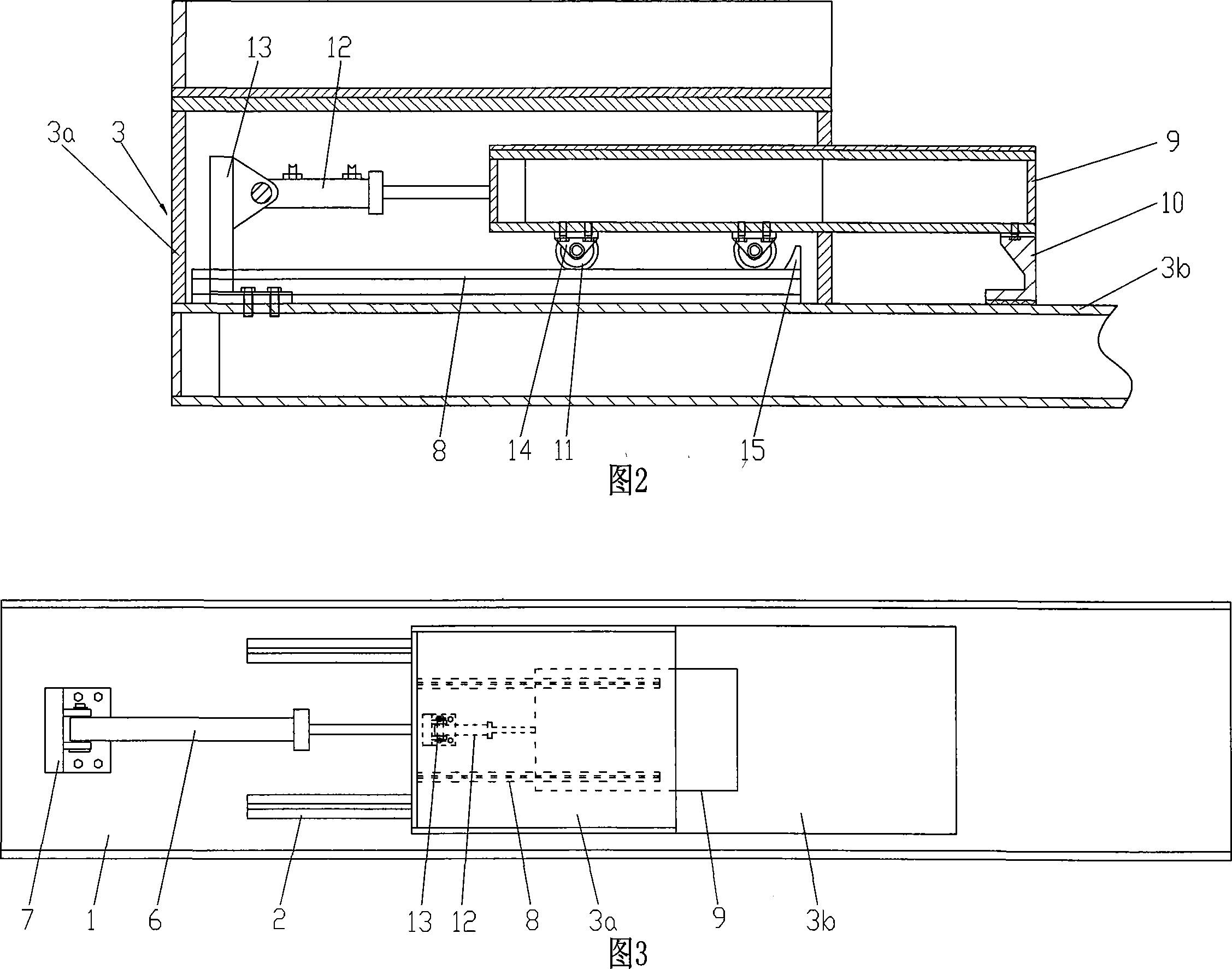
[0014] As shown in Figure 1, Figure 2 and Figure 3, the top plate 1a of the fixed chassis 1 is a flat plate structure parallel to the horizontal plane, and two rails 2 are arranged in parallel at the position behind the middle part of the top plate 1a of the fixed chassis 1, and the fixed chassis 1 1 The middle part of the rear end of the top plate 1a is bolted to the support 7, and the tail end of the hydraulic cylinder 6 parallel to the track 2 is connected to the support 7, and its piston rod protrudes forward and is fixedly connected to the rear end of the push cart 3. Pushing cart 3 is positioned at the below of feed bin 16, has the car body of upper and lower deck length unequal, wherein the rear end of upper strata car body 3a is aligned with the rear end of lower deck car body 3b, and the upper surface of upper strata car body 3a is positioned at upper...


PUM


Abstract

The present invention discloses a concealed garbage incineration charging equipment. It is characterized by that on the surface of lower layer carriage body of said charging carriage which is covered with upper layer carriage body two auxiliary guideway parallel to guideway are set, on said auxiliary guideway an auxiliary charging carriage is set, the front end of the described auxiliary charging caariage is extended from front end of upper layer carriage body of charging carriage, and is supported by wear-resistant slide block, in the rear portion of undersurface of said auxiliary charging carriage two wheels are mounted, said wheels are supported by correspondent auxiliary guideway, and can be forwards or backwards rolled. Said equipment can greatly raise charging efficiency.

Description

technical field [0001] The invention belongs to the technical field of waste incineration power generation, and in particular relates to a built-in waste incineration feeding device. Background technique [0002] At present, the feeding device used in the waste incineration power generation system is generally composed of fixed chassis, rails, push carts and hydraulic cylinders. Two rails are arranged in parallel on the upper surface of the fixed chassis, and the push cart is located above the rails. , has two upper and lower car bodies with unequal lengths, wherein the upper car body is aligned with the rear end of the lower car body, and a row of wear-resistant sliding blocks mainly for supporting and pushing materials are installed on the front end of the bottom surface of the lower car body. The rear part is connected to the wheel through the bearing, and the wheel is supported by the track, and can roll back and forth along the track. A pair of guide wheels separated o...

Claims


Application Information

Patent Timeline
IPC IPC(8): F23G5/44
Inventor 邵毅敏朱新才李长江林顺洪
Owner CHONGQING UNIVERSITY OF SCIENCE AND TECHNOLOGY
Why Eureka
Try Eureka