Multi-branch gas sampling pipe

A technology of gas sampling tubes and sampling tubes, applied in the direction of sampling devices, etc., can solve the problems of inconvenient calibration work, lengthened pipelines, increased gas pressure, etc., to achieve easy inspection and cleaning, reduce measurement errors, and reduce uncertainties Effect

A technology of gas sampling tubes and sampling tubes, applied in the direction of sampling devices, etc., can solve the problems of inconvenient calibration work, lengthened pipelines, increased gas pressure, etc., to achieve easy inspection and cleaning, reduce measurement errors, and reduce uncertainties Effect

CN101089587AInactive Publication Date: 2007-12-19PEKING UNIV

Image

  • Multi-branch gas sampling pipe
  • Multi-branch gas sampling pipe
  • Multi-branch gas sampling pipe

Examples


Embodiment Construction

[0018] The present invention will be described in detail below in conjunction with the accompanying drawings and embodiments.

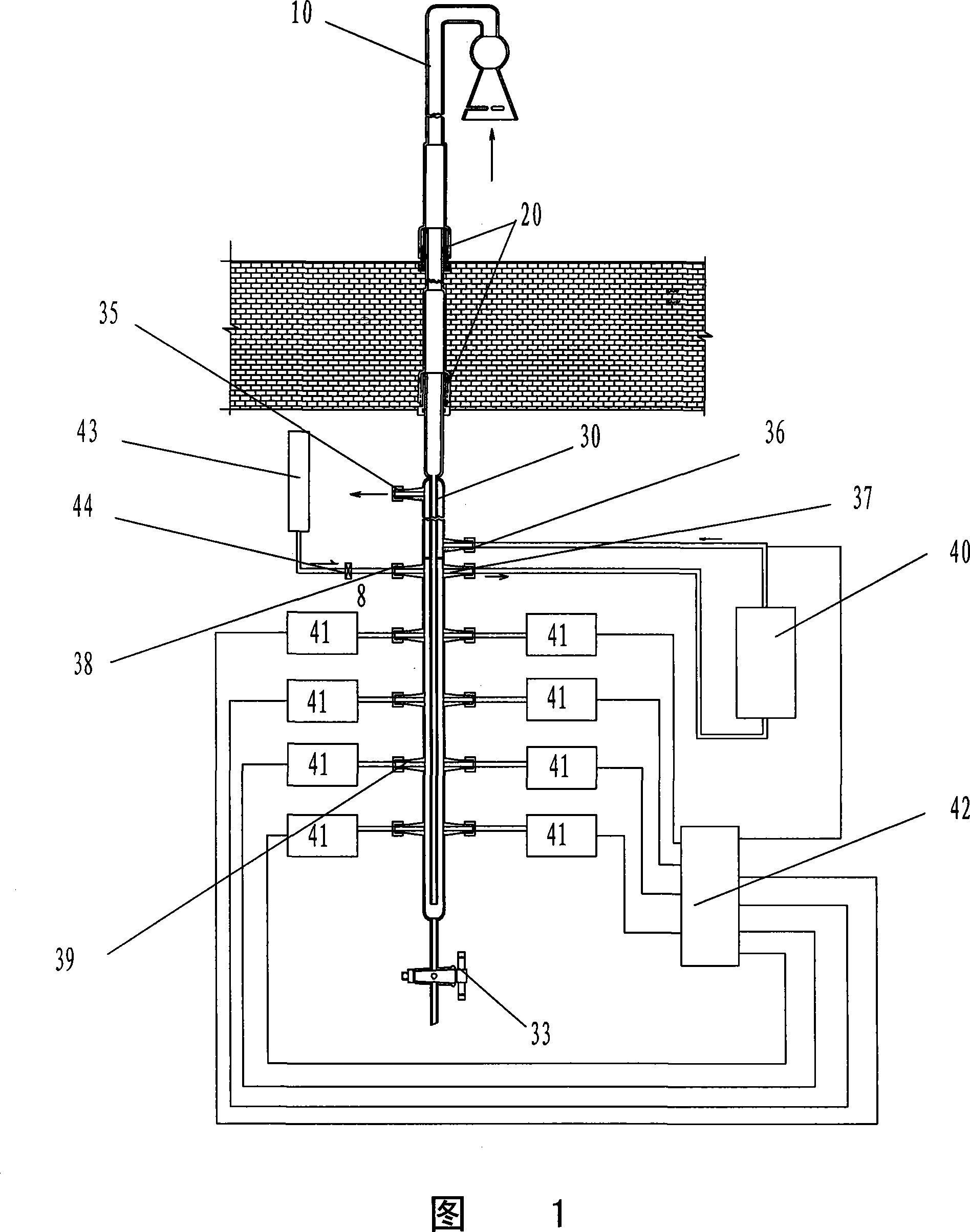
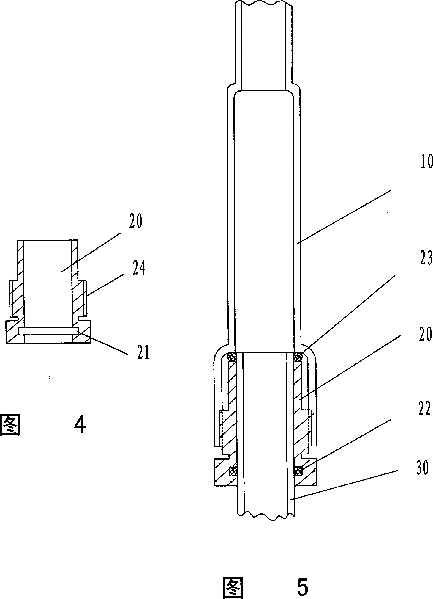
[0019] As shown in FIG. 1 , the multi-branch gas sampling tube of the present invention is mainly composed of three parts: a front-end sampling tube 10 , a pipe joint 20 and a main sampling tube 30 .

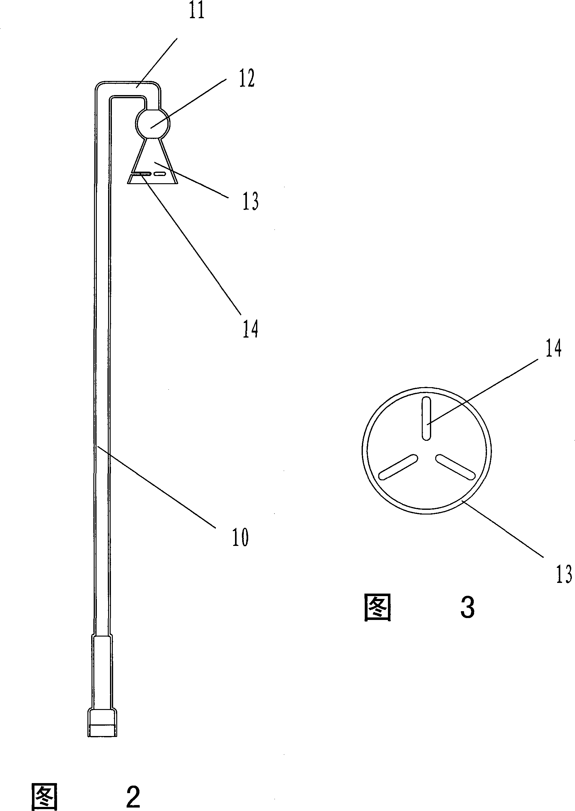
[0020] As shown in Fig. 1, Fig. 2 and Fig. 3, the front-end sampling pipe 10 made of glass material of the present invention refers to the pipeline above the main sampling pipe 30, which can be a pipe or a pipe joint 20 connected tube above the root. The uppermost end of the front-end sampling pipe is a U-shaped curved pipe 11, and the end of the curved pipe 11 is connected to an umbrella-shaped air inlet 13 through a spherical joint 12. Three to four ribs are arranged on the inner side of the umbrella-shaped air inlet 13, and the curved pipe 11 and the effect of umbrella-shaped air inlet 13 are rainproof and dustproof, and can prevent larger solid was...


PUM


Abstract

An air sampling tube with multiple branch is prepared as using tube fittings to connect master sampling tube to front end sampling tube, arranging an internal tube and an external tube on said master sampling tube, setting block plate at middle between said internal and external tubes, arranging an air vent and a hot air inlet at external tube above block plate, arranging a flow guide opening and a standard air inlet as well as multiple sample collection opening on external tube below block plate and connecting flow guide opening and standard air inlet as well as various sample collection openings separately to regulation port on a gate valve connected with flow guide pump.

Description

technical field [0001] The invention relates to a gas sampling tube, in particular to a multi-branch gas sampling tube. Background technique [0002] In order to accurately measure the concentration of harmful substances in the atmosphere, it is necessary to introduce the ambient atmosphere into an automatic monitoring station and send it to various gas analysis instruments for detection. During the transportation of the sample, the external environment may change (meteorological conditions such as temperature and humidity), how to keep the state unchanged, that is, the sample gas does not condense, the residence time is short and can be controlled, it is necessary to design a special sampling header. At the same time, the sampling main pipe should also have the function of calibrating various environmental detection instruments with standard gases. When using the traditional method to calibrate the instrument, three-way solenoid valves and TEFLON (polytetrafluoroethylene) ...

Claims


Application Information

Patent Timeline
19 Dec 2007
Publication
CN101089587A
IPC
G01N1/24
Inventors
曾立民