
Device for producing iron core

A technology for manufacturing devices and iron cores, which is applied in the field of winding iron core manufacturing devices, and can solve problems such as quality reduction, steel strip bending or cutting length errors, and scratches on the side of the iron core.

Inactive Publication Date: 2007-12-19
DAIHEN CORP
View PDF1 Cites 2 Cited by
  • Summary
  • Abstract
  • Description
  • Claims
  • Application Information

AI Technical Summary

Problems solved by technology

For such an iron core, after annealing to remove the warpage of the iron core in the subsequent process, the iron core disintegrates together, and it is difficult to return to the original shape of the iron core when it is assembled with the coil winding. It requires a lot of force to restore it, and it is difficult to work manually. In addition, when the tension is applied, the steel belt is sometimes pulled, causing the offset of the overlapping position and making defective products.
On the other hand, relative to the winding-in speed of the steel strip, when the feeding speed of the steel strip is fast, the steel strip slacks, causing bending or cutting length errors of the steel strip, scratches on the side of the iron core or large or small overlaps, reducing quality

Method used


Image

  • Device for producing iron core
  • Device for producing iron core
  • Device for producing iron core

Examples


Embodiment Construction

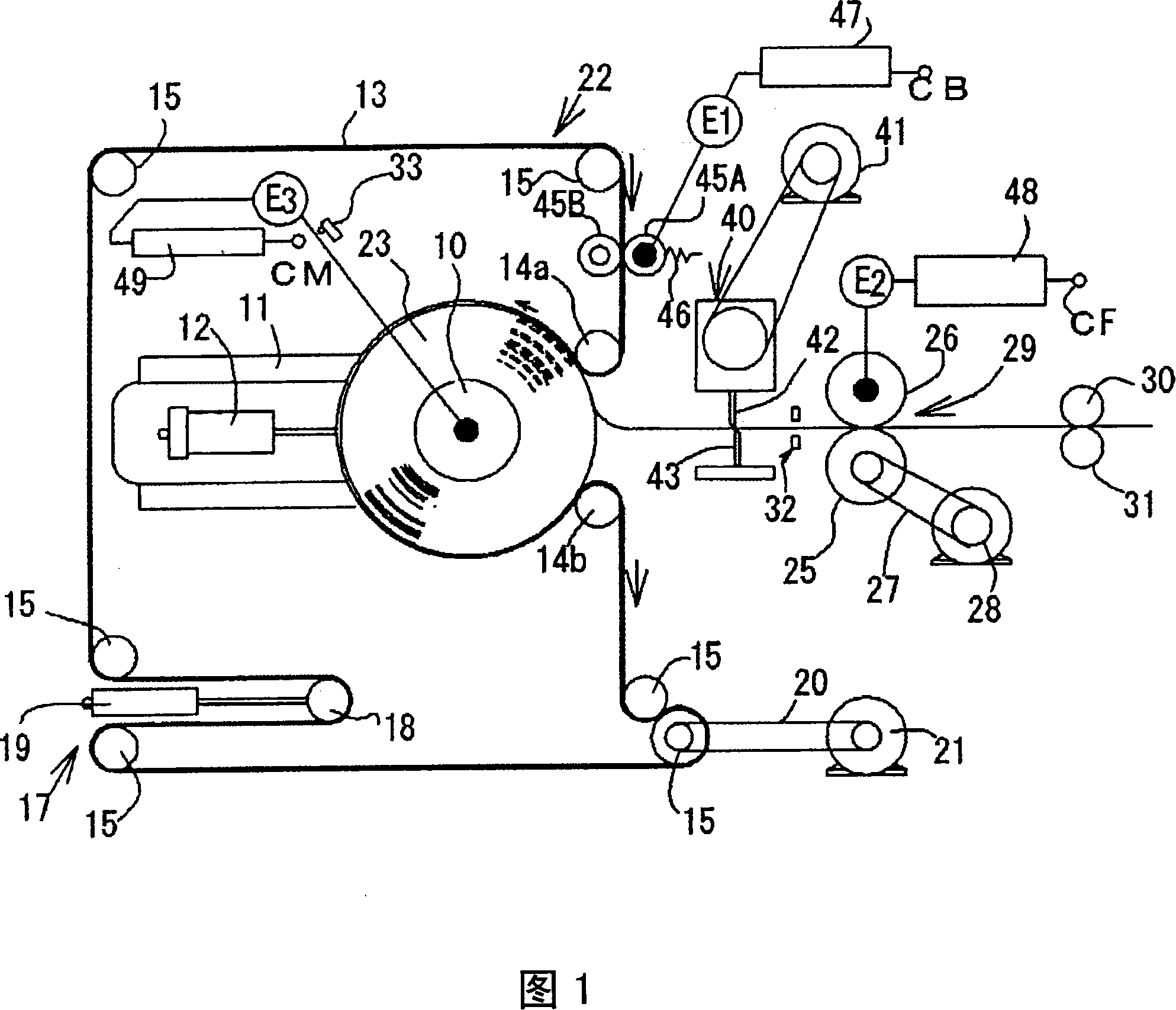
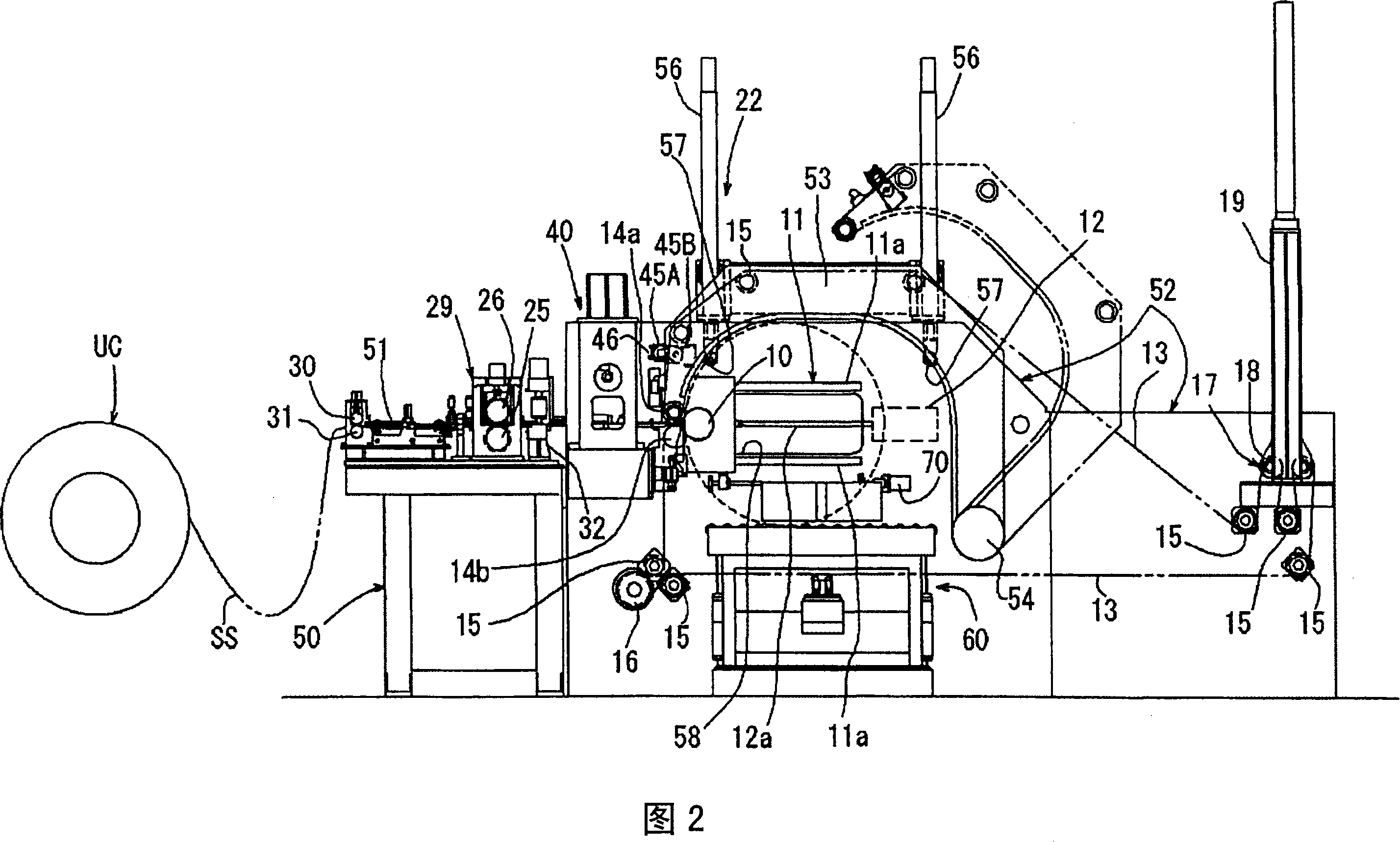
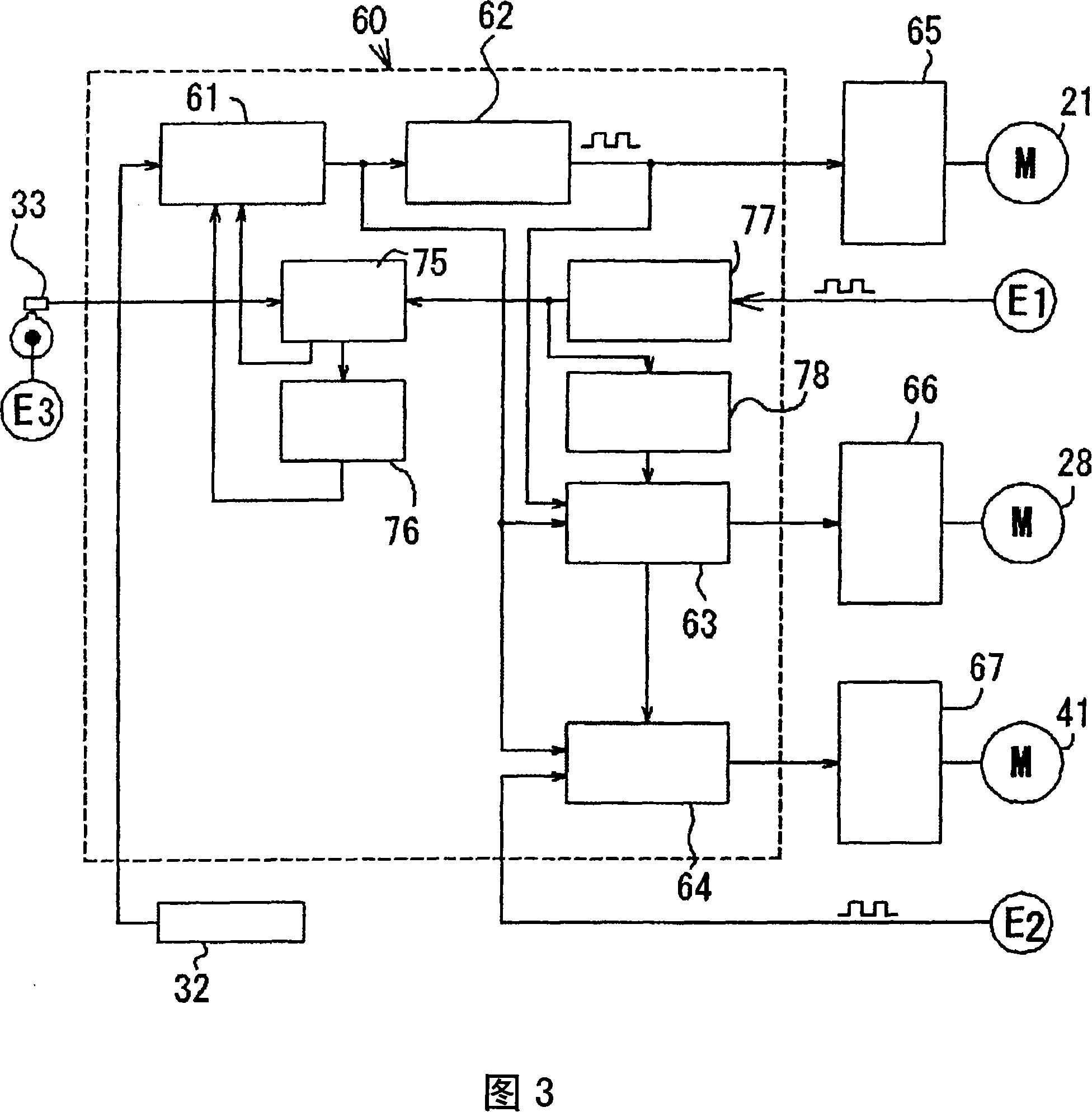
[0058] FIG. 1 is a diagram schematically showing the mechanical configuration of an embodiment of the present invention. In this figure, 10 is a winding frame mounted on a rotating shaft supported freely movable in the horizontal direction by a slide device 11, and 12 is a winding frame. Frame 10 is a cylinder that exerts force to the left on the drawing, and 13 is an endless winding belt, which is erected on winding frame 10; guide pulleys 14a, 14b supported in a fixed place near winding frame 10; Guide pulleys 15, 15, . . . around the frame 10; a drive pulley 16; The pulley 18 of the animal energy device is connected to the piston rod of the air cylinder 19 , and the pulley 18 is biased to the right on the screen by the air cylinder 19 to give tension to the belt 13 . The driving pulley 15 is connected to the belt motor 21 via the belt 20, and the winding belt 13 is driven in the direction of the arrow shown in the figure by the rotation of the driving pulley 15, and the win...


PUM


Abstract

The invention relates to a winding core manufacturing device, comprising: coiling device (22) for winding the metal strip (SS) between winding frame (10) and coiling strips (13) to wind the winding core (23); metal strip supplying machine (29) for sending the metal strip to supply roller (25); clipper (40) installed between the coiling device and metal strip supplying machine and cutting the metal strip without stopping it. The metal strip supplying machine is controlled to send metal strip at the speed equal to coiling speed of metal strip of the coiling device. When the metal strip supplying machine supples the metal strip of preset length, the said metal strip is cut by clipper for unit metal strip to continuously wind the winding core. The cut length is calculated based on the thickness of metal strip calculated by strip length of each revolution of the winding frame. Therefore, the invention can produce a number of iron core of high quality with proper clearance between each butt-joint part or lapping amount.

Description

technical field [0001] The present invention relates to a wound core manufacturing apparatus for manufacturing a wound core by winding a steel strip between a winding frame and a winding belt to wind a steel strip around a winding frame. Background technique [0002] The wound core has the following structure: the unit steel strip is wound into one turn and the two ends are lapped (overlapped) with a specified lap amount (ラツプデ) or the lap is zeroed (突き合わせ) to form multiple layers. A plurality of laminated structures of laminated core blocks. [0003] FIG. 15 shows an example of a circular wound core structure. In this core, three core blocks B1 to B3 are provided. The three core blocks are formed so as to connect the junctions (overlapped parts or The butt joints) J are distributed in a step-like state in approximately the same range. [0004] When manufacturing a wound core, a winding frame is used to wind a plurality of unit steel strips around the winding frame, but in ...

Claims


Application Information

Patent Timeline
IPC IPC(8): H01F27/25H01F41/02
Inventor 有坂宏平
Owner DAIHEN CORP
Learn More