Motor for washer and roller type washer
A drum-type washing machine and motor technology, which is applied in the field of drum-type washing and drying machines and motors, can solve the problems of helpless motors, deterioration of productivity, and unfavorable cost reduction, and achieve the effect of large torque and easy assembly
- Summary
- Abstract
- Description
- Claims
- Application Information
AI Technical Summary
Problems solved by technology
Method used
Image

Examples
Embodiment approach 1
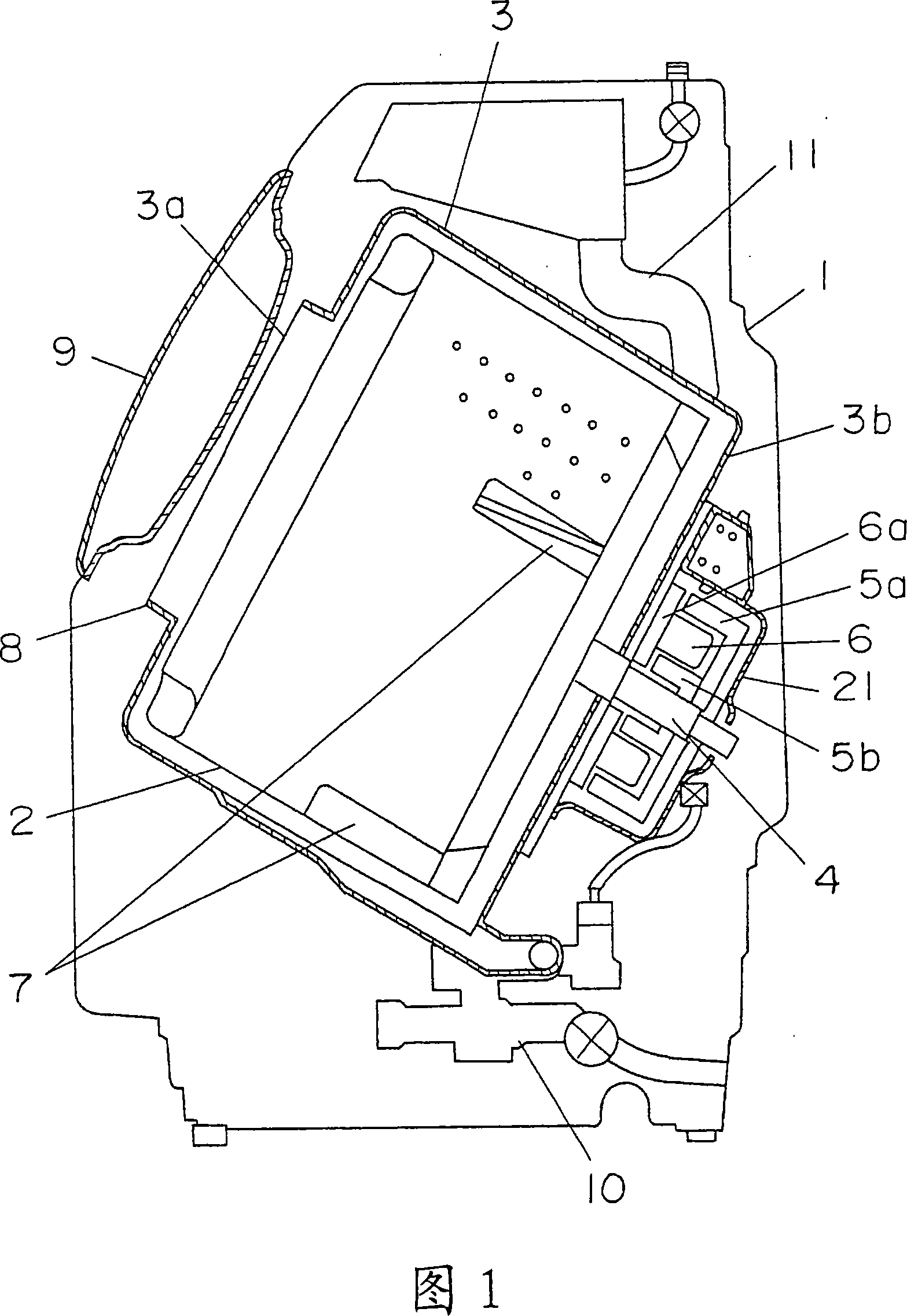
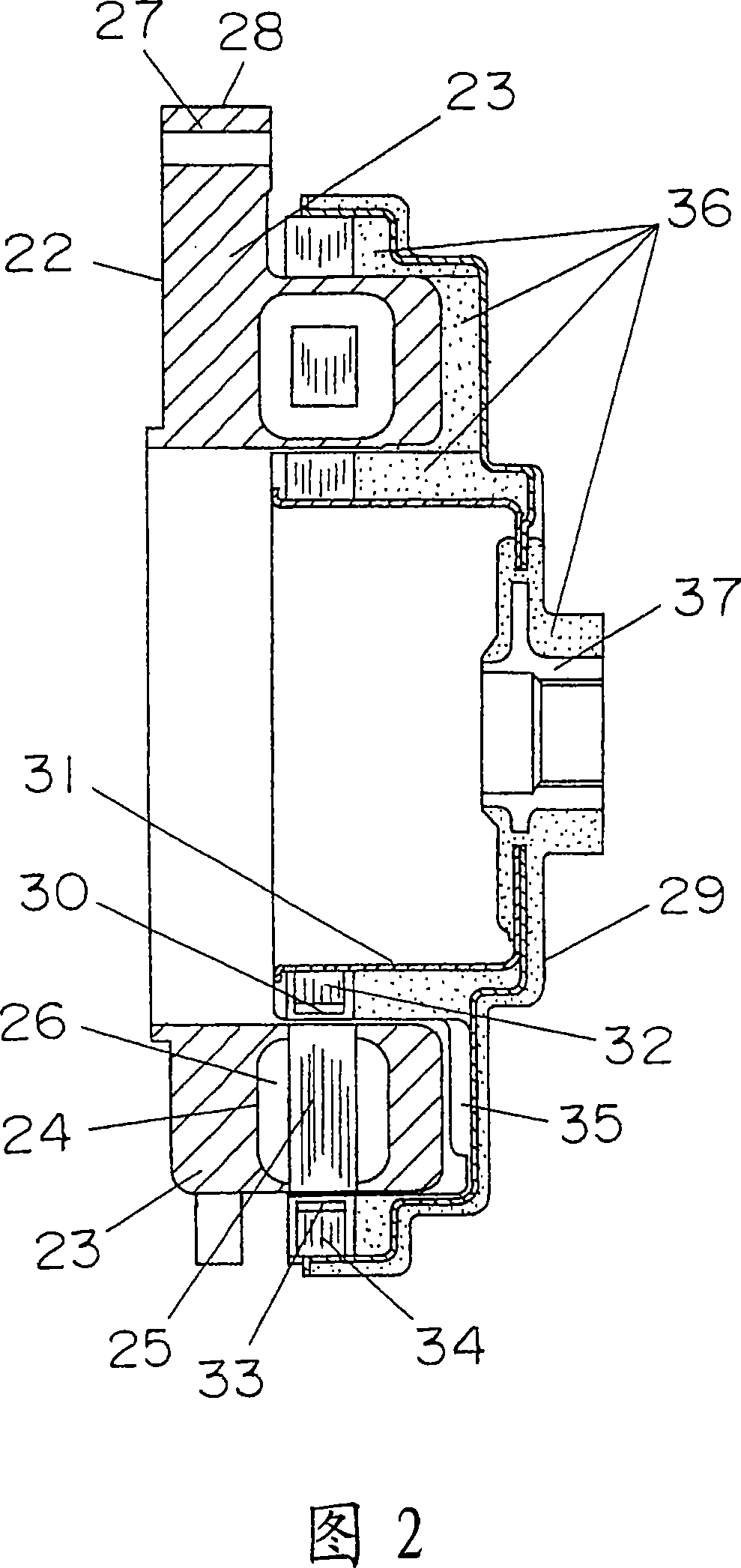
[0038] 1 is a schematic cross-sectional view of a front-loading washing machine according to a first embodiment of the present invention, and FIG. 2 is a main-part cross-sectional view of a motor of the front-loading washing machine.
[0039] In FIG. 1 , the same components as those shown in FIG. 5 or FIG. 6 of the conventional example will be described with the same reference numerals.
[0040] In Fig. 1, a drum type washing machine main body 1 has a built-in water tub 3 and a rotating drum 2 rotatably arranged in the water tub 3, and a rotating shaft 4 is provided at the center of rotation of the rotating drum 2 in a substantially inclined direction, so that the rotating drum The axial direction of 2 is inclined downward from the front side toward the back side, and the motor 21 is installed on the back side of the bucket 3, that is, the outer bottom surface 3b.
[0041] The stator 6 of the motor 21 is fixed on the bottom surface of the bucket 3 through the installation unit...
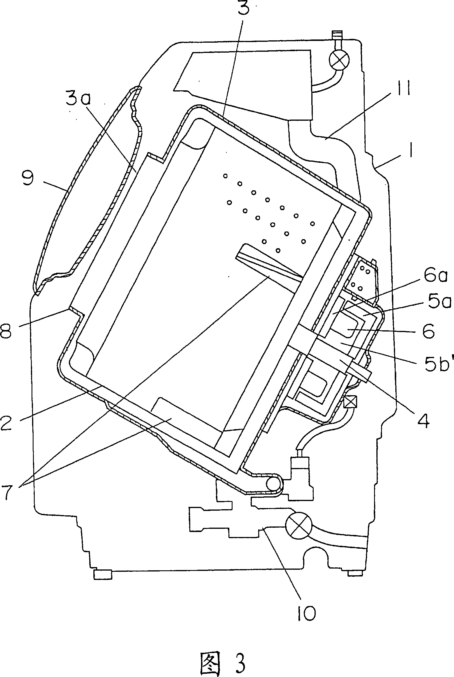
Embodiment approach 2
[0054] The mounting sleeve 37 is fixed on the rotating shaft 4 in FIG. 1 and is used to rotate the rotating drum 2 .
[0055] According to the above structure, by arranging both the outer rotor and the inner rotor, the space usable as a motor can be utilized to the maximum. As a result, the torque generated per unit space increases, so that the motor torque can be increased or the motor can be reduced in size, thereby increasing the capacity and reducing the size of the front-loading washing machine.
PUM
 Abstract
Description
Claims
Application Information
 - Generate Ideas
- Intellectual Property
- Life Sciences
- Materials
- Tech Scout
- Unparalleled Data Quality
- Higher Quality Content
- 60% Fewer Hallucinations
Browse by: Latest US Patents, China's latest patents, Technical Efficacy Thesaurus, Application Domain, Technology Topic, Popular Technical Reports.
© 2025 PatSnap. All rights reserved.Legal|Privacy policy|Modern Slavery Act Transparency Statement|Sitemap|About US| Contact US: help@patsnap.com