
Radio terminal performance test device and method

A wireless terminal and testing device technology, which is applied in the direction of selection device, wireless communication, radio/induction link selection arrangement, etc., can solve the problem that the signal strength and transmission power cannot be accurately controlled, the test results are not comparable, and the human radiation hazard is great. To overcome the defects of power consumption and thermal test methods, the test results are accurate and repeatable, and the effect of reducing external radiation

Active Publication Date: 2007-12-19
HUAWEI TECH CO LTD
View PDF0 Cites 59 Cited by
  • Summary
  • Abstract
  • Description
  • Claims
  • Application Information

AI Technical Summary

Problems solved by technology

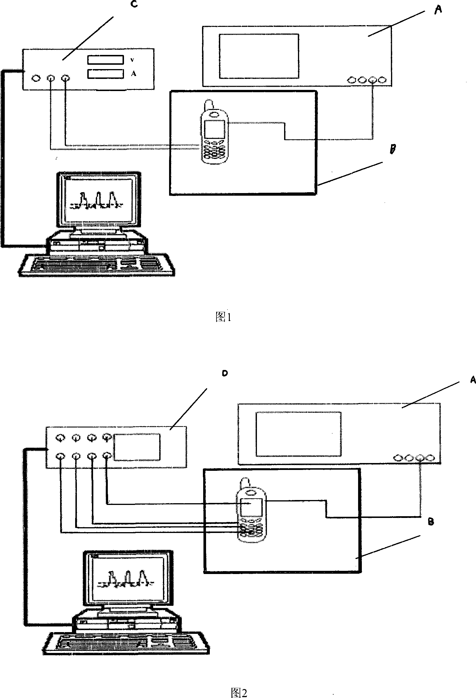
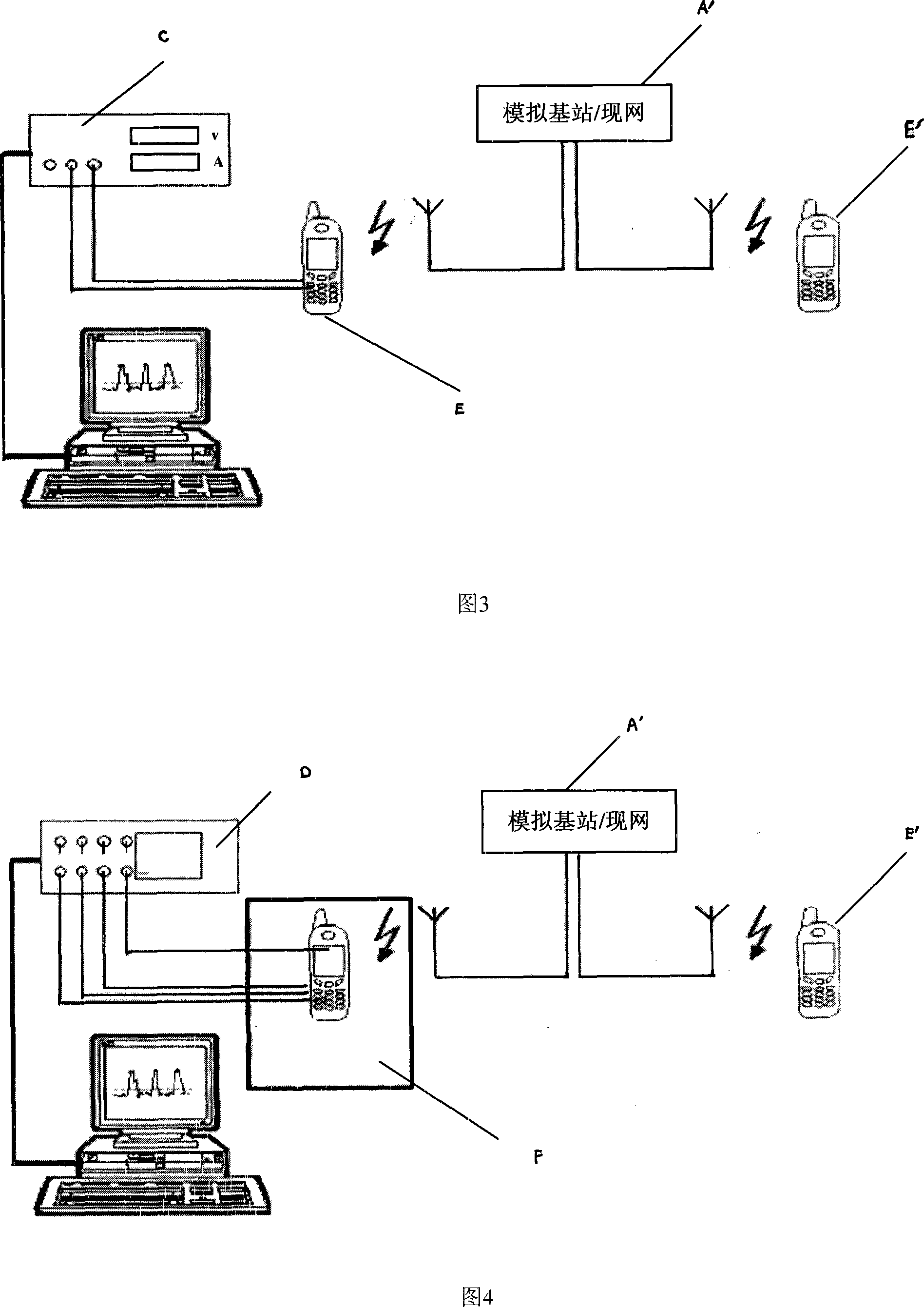
[0007] In the process of realizing the present invention, the inventor finds that the second test method has at least the following problems: although the second test method overcomes the deficiencies of the first method and can test wireless indicators, it still has the following defects: (1) Under the influence of multi-channel effect, the signal strength and transmission power received by mobile phones cannot be accurately controlled, and the test results in different locations are not comparable; (2) other external interference (such as different time periods during the day and night, different weather conditions, etc.) Uncontrollable, and the test done by the antenna connected to the simulated base station is a near-field test. Uncontrollable interference factors will lead to poor repeatability of the test; (3) When the mobile phone transmits at high power, it will cause great harm to the human body. The health of the testers is unfavorable; under the same transmission power, due to the influence of external conditions, the test results may have relatively large differences, and the repeatability is poor. The test results are only for reference and cannot be used as research, testing and inspection standards.

Method used


Image

  • Radio terminal performance test device and method
  • Radio terminal performance test device and method
  • Radio terminal performance test device and method

Examples


Embodiment Construction

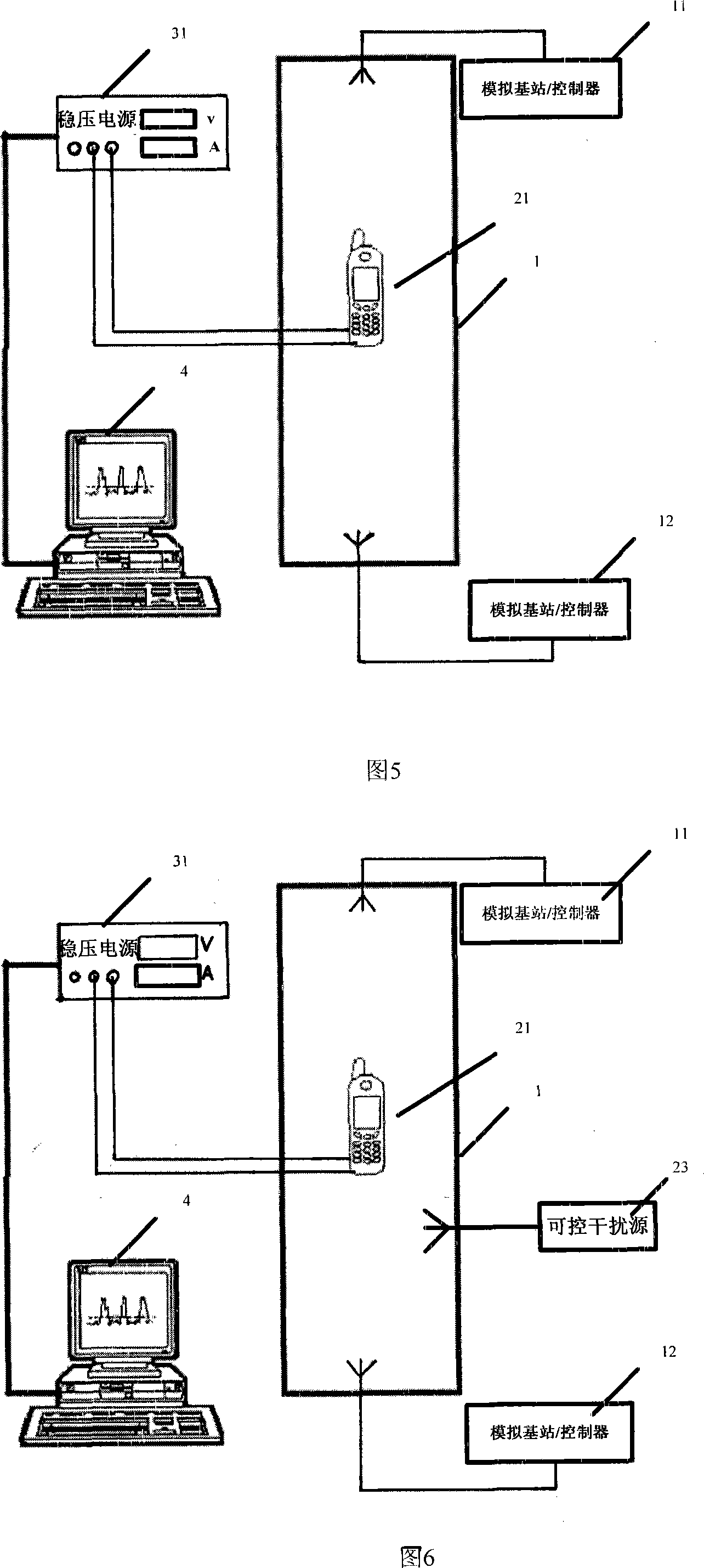
[0031] Referring to FIG. 5 , it is a first implementation manner of testing terminal power consumption by a wireless terminal performance testing device according to the present invention. As shown in Figure 5, the wireless terminal performance testing device described in this embodiment includes:

[0032] Shielding box 1, there are 2 antennas inside the shielding box 1, the first antenna is connected to the analog base station / controller 11 outside the shielding box through a radio frequency cable; the second antenna is connected to the analog base station / controller 12 through a radio frequency cable Two antennas are arranged in the shielding box, and the signal strength transmitted to the tested mobile phone 21 is controlled by the simulated base station / controller 11 and / or simulated base station / controller 12, so that the received signal of the tested mobile phone can be artificially controlled, thereby testing the mobile phone Power consumption under different transmissi...


PUM


Abstract

This invention discloses a performance test device and a method for radio terminal, in which, the device includes: a shield box with at least one antenna connected with an analog base station / controller out of the shield box, a test instrument connected with the being tested terminal in the box to test its radio performance, which controls the signal strength emitted to the radio terminal by the analog base station / controller, so that emitted signals can be controlled artificially, besides, tested terminals can work under single or multiple nets since one or many antennas are set in the box and shields radiation to outside test equipment and personnel and shields influence to being tested terminal from outside radiation interference of outside magnetic environment to guarantee accuracy of test result.

Description

technical field [0001] The present invention relates to a wireless terminal performance testing device, in particular to a terminal wireless performance testing device which can work in a single or multi-network condition, reduce test radiation and improve test repeatability; the present invention also relates to A wireless terminal performance test method, in particular a wireless terminal performance test method that enables the test environment of the terminal to be tested to be controlled, reduces test radiation and improves test repeatability, and belongs to the technical field of wireless communication. Background technique [0002] With the development and popularization of wireless communication technology, mobile phones have become the mobile information center of daily life. Standby and talk time are technical indicators that mobile phones, operators and ordinary consumers care about. General standby time=battery capacity / standby current; talk time=battery capacit...

Claims


Application Information

Patent Timeline
IPC IPC(8): H04Q7/34H04B17/00H04M1/24H04W24/00
Inventor 靳林芳杨丽萍薛林华文丽
Owner HUAWEI TECH CO LTD
Learn More