Vaporizing device and liquid absorbing portion

A technology of evaporating devices and absorbing parts, applied in the direction of boiling devices, feeding devices, inorganic chemistry, etc., can solve the problems of small size of evaporating devices, difficulty in evaporating fuel stably or in large quantities, etc.

Inactive Publication Date: 2013-12-04
CASIO COMPUTER CO LTD
View PDF14 Cites 0 Cited by
  • Summary
  • Abstract
  • Description
  • Claims
  • Application Information

AI Technical Summary

Problems solved by technology

[0004] However, the evaporation device is made smaller in size, and it becomes difficult to vaporize the fuel stably or in large quantities

Method used


Image

  • Vaporizing device and liquid absorbing portion
  • Vaporizing device and liquid absorbing portion
  • Vaporizing device and liquid absorbing portion

Examples


Embodiment Construction

[0043] Here, preferred embodiments of the present invention will be described with reference to the accompanying drawings. Although various preferable technical limitations are added to the embodiments described later, these embodiments are by no means intended to limit the scope of the present invention to the embodiments described later and the drawings.

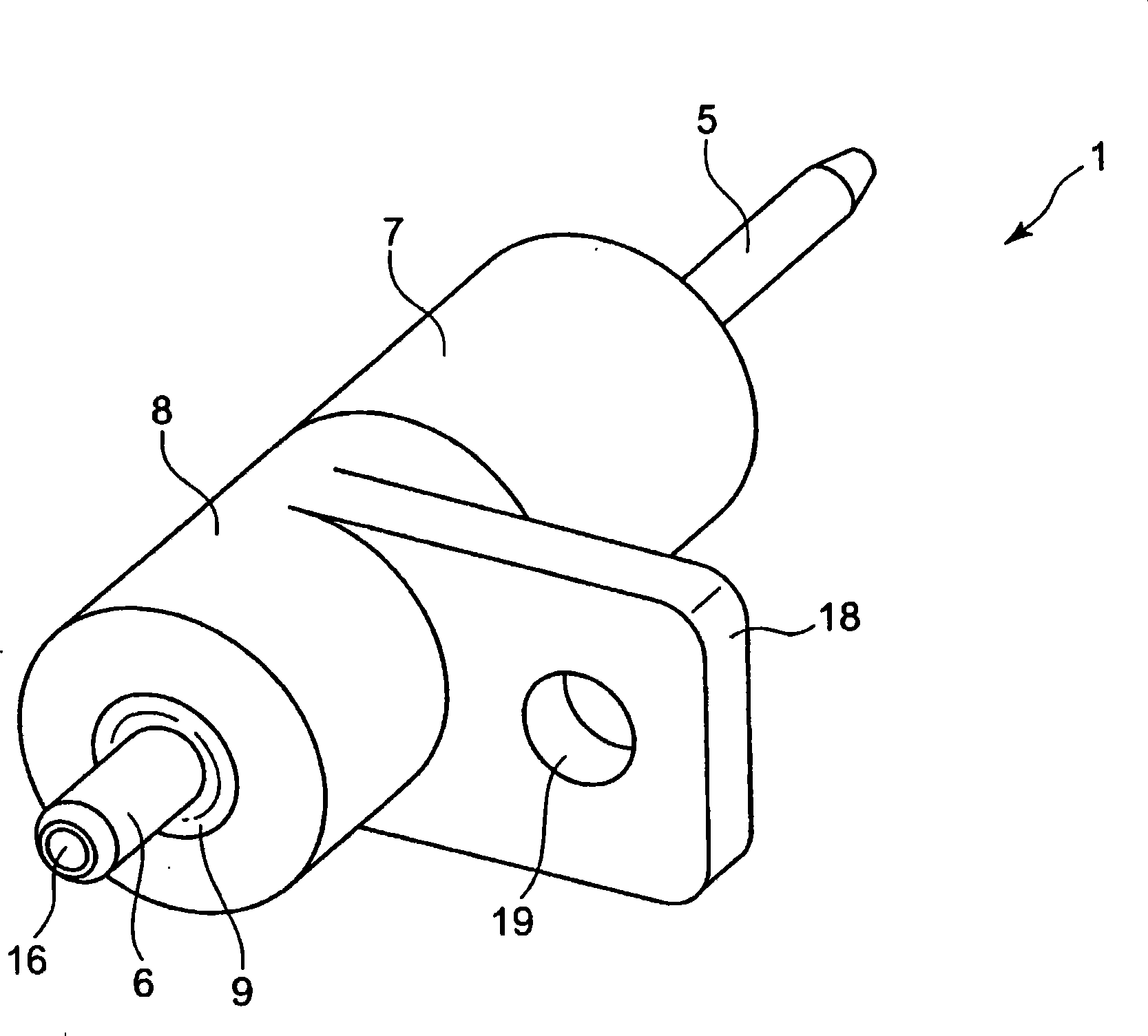
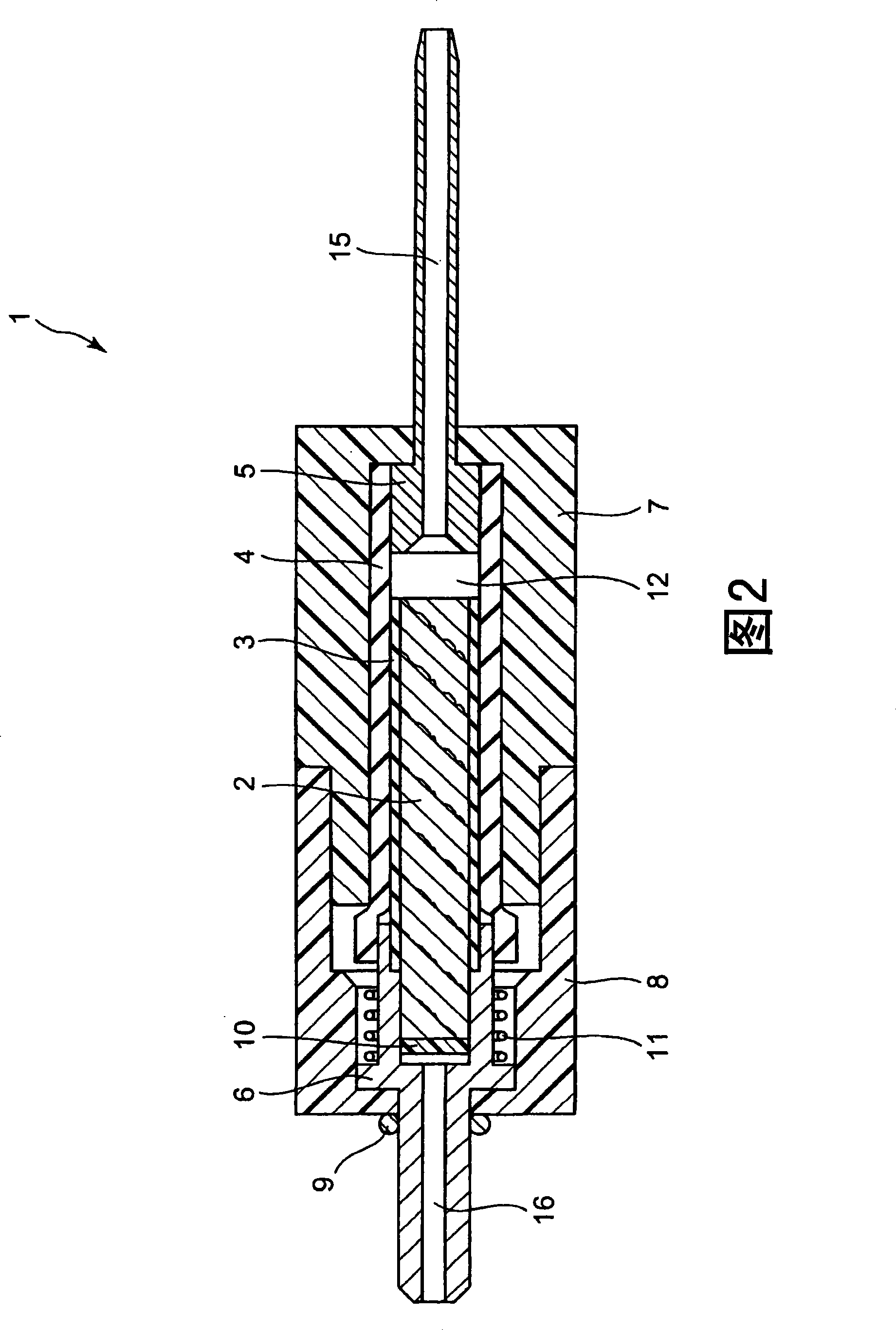
[0044] figure 1 is a perspective view showing the evaporation device 1, figure 2 is a cross-sectional view of the evaporation device 1 along its center line.

[0045] Such as figure 1 and figure 2 As shown, the evaporation device 1 includes a liquid absorbing member 2 having a property of absorbing liquid therein, an inner tube 3 partially covering the outer peripheral surface of the liquid absorbing member 2, and an outer tube 4 covering the outer peripheral surface of the inner tube 3 through which the liquid passes. An inlet nozzle 5 flowing into the liquid-absorbing member 2, an outlet nozzle 6 through which the ...


PUM

PropertyMeasurementUnit
pore sizeaaaaaaaaaa
thicknessaaaaaaaaaa
pore sizeaaaaaaaaaa

Abstract

PROBLEM TO BE SOLVED: To stably vaporize fuel in a vaporizing device.SOLUTION: A liquid absorbing portion 2 is fitted in a heat shrinkable inner tube 3, and an outer peripheral face of the liquid absorbing portion 2 is closely kept into contact with the inner tube 3. The liquid absorbing portion 2 and the inner tube 3 are inserted into an outer tube 4, a part of a tubular inlet nipple 5 is fitted to one end portion of the outer tube 4, and a part of an outlet nipple 6 is inserted into the other end portion of the outer tube 4. A heat generating coil 11 is wound on a part of the outlet nipple 6. The outer tube 4, the inner tube 3, the liquid absorbing portion 2 and the heat generating coil 11 are inserted into an inlet case 7 and an outlet case 8.

Description

technical field [0001] The present invention relates to an evaporating device for evaporating liquid, and a liquid absorbing member used in the evaporating device. Background technique [0002] Recent years have seen intensive research and development for fuel cells to achieve high energy usage efficiency. A fuel cell electrochemically reacts a fuel with oxygen contained in ambient air and obtains electrical energy directly from the chemical energy. Fuel cells have emerged as a promising energy source. As fuel used in fuel cells, mention may be made of hydrogen. One problem, however, is that hydrogen is difficult to handle and store since it is a gas at ambient temperature. When using liquid fuels like alcohols and gasoline, the systems used to store the liquid fuels can be made relatively small, but the fuel and water vapor must be heated to high temperatures to react to produce hydrogen for power generation . [0003] For example, in Japanese Laid-Open Patent Specific...

Claims


Application Information

Patent Timeline
Patent Type & Authority Patents(China)
IPC IPC(8): C01B3/32B01J4/04B01J4/00B01B1/00
CPCY02E60/50
Inventor 椛泽康成今中大介齐藤馨
Owner CASIO COMPUTER CO LTD
Why Eureka
Try Eureka