A solar water evaporation purification and decomposition device

Active Publication Date: 2021-06-11
西安秦盛丰科技有限公司
View PDF5 Cites 0 Cited by
  • Summary
  • Abstract
  • Description
  • Claims
  • Application Information

AI Technical Summary

Problems solved by technology

At present, the research on photocatalytic water splitting mainly focuses on powder catalysts, and the research on the design of integrated photocatalytic hydrogen production devices is relatively lacking.

Method used


Image

  • A solar water evaporation purification and decomposition device
  • A solar water evaporation purification and decomposition device
  • A solar water evaporation purification and decomposition device

Examples


Embodiment 1

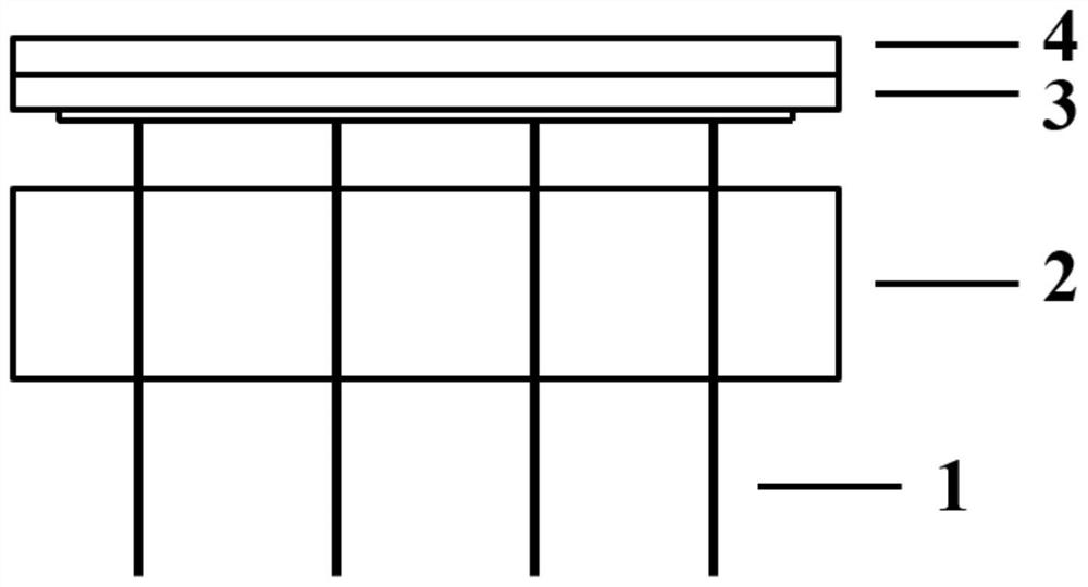
[0028] Using oleylamine as the reaction solvent and surfactant, copper acetate, stannous chloride, and selenium dioxide as reactants, a one-pot thermal decomposition method was used to synthesize hydrophobic Cu 2 SnSe 3 porous nanospheres. Will Cu 2 SnSe 3 After the porous nanospheres are centrifugally cleaned, they are dispersed in cyclohexane and vacuum filtered onto the hydrophilic mixed cellulose membrane to form a hydrophilic / hydrophobic double-layer evaporation structure as the evaporation layer (3) / light-to-heat conversion and solute barrier layer (4). Polyurethane foam is used as the floating and insulating layer (2), and a water-absorbing non-woven fabric is used as the water supply line (1).

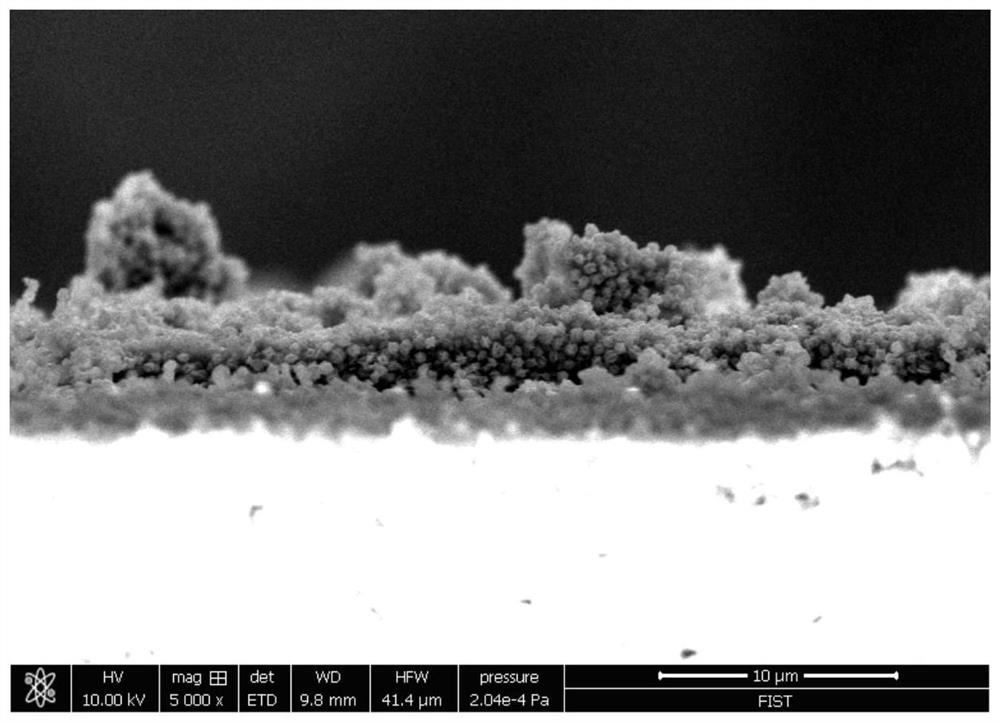
[0029] see figure 2 , an obvious double-layer structure with abundant channels was observed by scanning electron microscope;

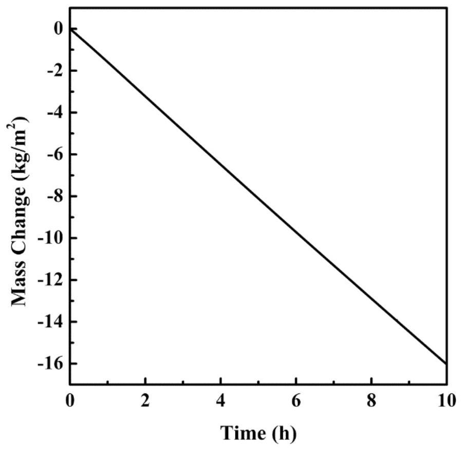
[0030] see image 3 , Bohai sea water evaporation results show that the device has a stable evaporation rate;

[0031] see Figure 4 , Figu...

Embodiment 2

[0033] P25TiO was screen-printed 2 Coated with CdTe slurry on the porous water-absorbing ceramic sheet, and formed a porous layer after annealing. The uppermost layer material is hydrophobically modified with heptadecafluorodecyltrimethoxysilane solution to form a hydrophilic / hydrophobic double-layer evaporation structure as the evaporation layer (3) / light-to-heat conversion and solute blocking layer (4). Polystyrene foam is used as the floating and insulating layer (2), and absorbent filter paper is used as the water supply line (1).

Embodiment 3

[0035] Hexadecylamine is used as surfactant, ethylene glycol is used as solvent, cupric chloride, zinc acetate, stannous chloride, and thiourea are used as raw materials, and sol-gel method is used to spin-coat on the surface of hydrophilic filter paper, and it is formed after heat treatment. Hydrophobic Cu 2 ZnSnS 4 The porous layer forms a hydrophilic / hydrophobic double-layer evaporation structure as an evaporation layer (3) / light-to-heat conversion and solute blocking layer (4). Polyethylene foam is used as the floating and insulating layer (2), and absorbent cotton is used as the water supply line (1).


PUM

PropertyMeasurementUnit
photothermal conversion efficiencyaaaaaaaaaa

Abstract

A solar water evaporation purification and decomposition device comprises a water supply line, a floating and heat insulating layer, an evaporation layer, a light-to-heat conversion and a solute blocking layer connected sequentially from bottom to top. The water supply line uses capillary action to pump water through the floating and thermal insulation layer to the evaporation layer. The light-to-heat conversion and solute barrier layer absorbs solar energy and converts it into heat, and the heated water is vaporized from the evaporation layer to water vapor. Through the light-to-heat conversion and solute barrier The pores of the layer are volatilized, and part of the water vapor is decomposed to produce hydrogen and oxygen. Since the light-to-heat conversion and solute barrier layer contains hydrophobic parts, it will not be infiltrated by water, so solar energy can only directly heat the heat-absorbing material without heating water to achieve high light intensity. Heat conversion efficiency, while preventing solutes in water from being precipitated on the surface of the membrane, to achieve seawater desalination, sewage purification and water splitting. The invention obtains a solar water evaporation purification and decomposition device with high light-to-heat conversion efficiency and high stability through the design of a hydrophilic / hydrophobic double-layer evaporation structure.

Description

technical field [0001] The invention belongs to the technical fields of material chemistry and solar energy conversion, and in particular relates to a solar water evaporation purification and decomposition device. Background technique [0002] With the rapid development of industrialization, energy and environmental issues have become two major factors restricting the development of human society. The acquisition of fresh water resources and clean energy is very important. Among them, seawater desalination to obtain fresh water, sewage treatment and hydrogen energy have become the current research hotspots. Seawater covers 70.8% of the earth's surface, accounting for 97% of the world's water, and is considered an unlimited water resource. At present, membrane and thermal seawater desalination have been put into practical use and produced a large amount of fresh water. However, these two technologies have problems such as complex pretreatment, large energy consumption, and g...

Claims


Application Information

Patent Timeline
Patent Type & Authority Patents(China)
IPC IPC(8): C02F1/04C02F1/14C01B3/04C01B13/02C02F103/08
CPCC01B3/045C01B13/0207C01B2203/0266C02F1/048C02F1/14C02F2103/08Y02E60/36Y02P20/133Y02A20/124Y02A20/142Y02A20/212
Inventor 阙文修杨亚威杜亚平
Owner 西安秦盛丰科技有限公司
Why Eureka
Try Eureka