Frameless upright rolling mill with short stress trajectory

A short stress line, frameless technology, applied in the direction of metal rolling mill stands, metal rolling, metal rolling, etc., can solve the problems of reducing equipment work efficiency, frequent changes of rolling lines, and difficulty in mechanical processing, etc., and achieve processing operations And the effect of convenient roll change, light weight, and reduction of production accidents

Inactive Publication Date: 2007-12-26
UNIV OF SCI & TECH BEIJING +1
View PDF1 Cites 3 Cited by
  • Summary
  • Abstract
  • Description
  • Claims
  • Application Information

AI Technical Summary

Problems solved by technology

[0004] The purpose of the present invention is to cancel the large and small frame structures of the traditional vertical rolling mill and replace them with an open U-shaped frame structure, so as to solve the problems of heavy weight, difficult mechanical processing, large processing volume and high cost of the frame vertical rolling mill, and at the same time solve the problems of During the adjustment process of the frame vertical rolling mill, the rolling line changes frequently and the adjustment is difficult, which reduces the working efficiency of the equipment.

Method used


Image

  • Frameless upright rolling mill with short stress trajectory
  • Frameless upright rolling mill with short stress trajectory
  • Frameless upright rolling mill with short stress trajectory

Examples


Embodiment Construction

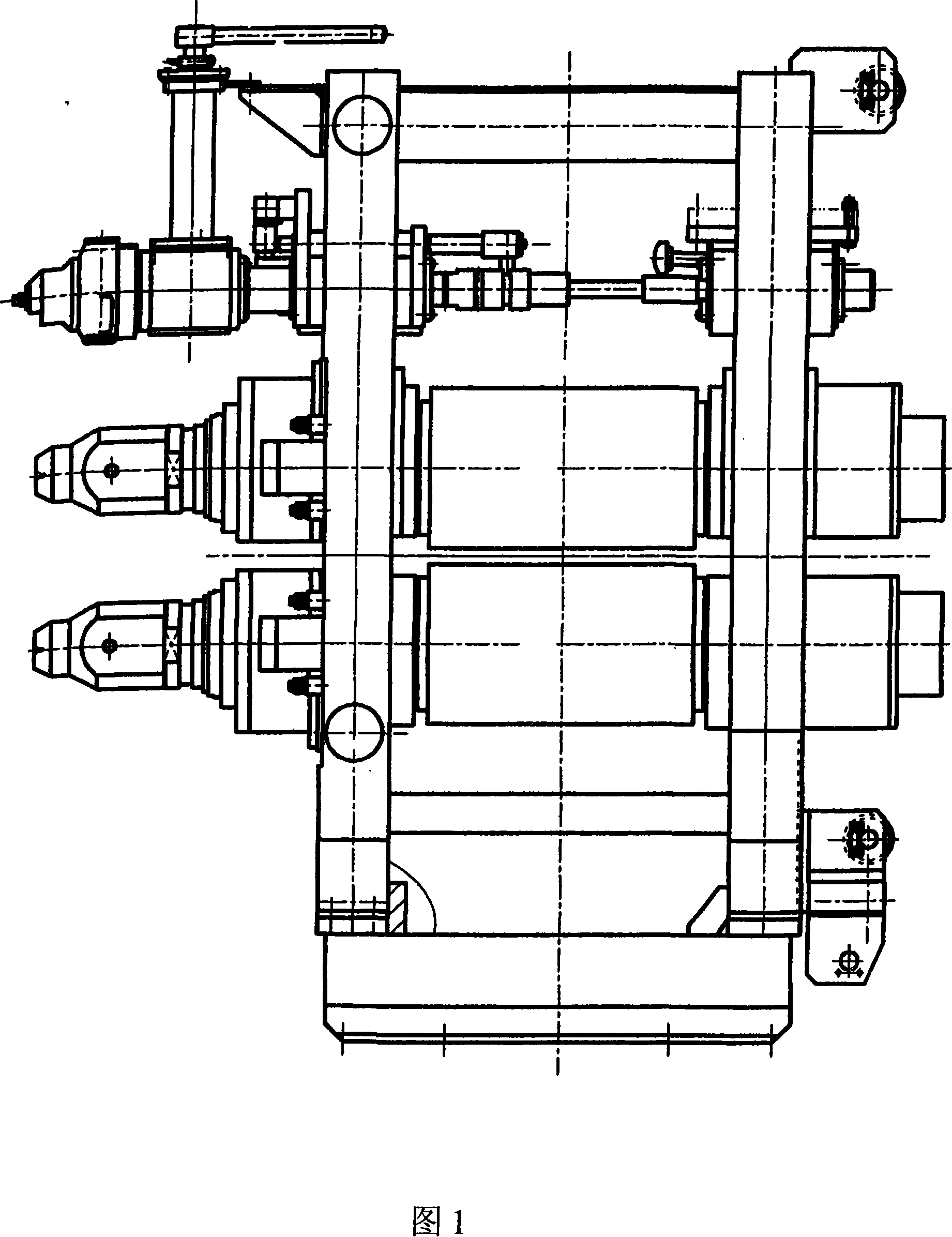
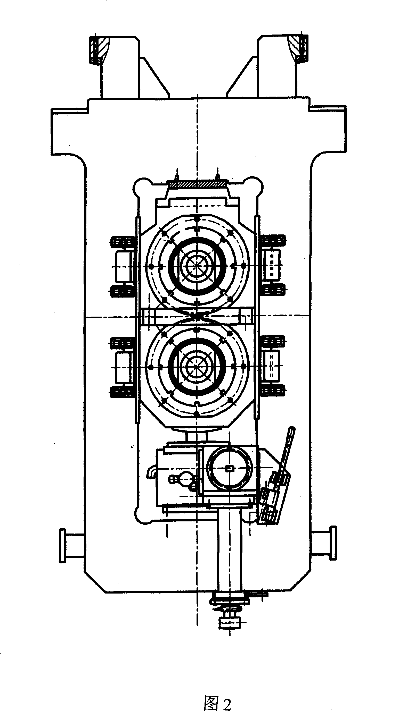
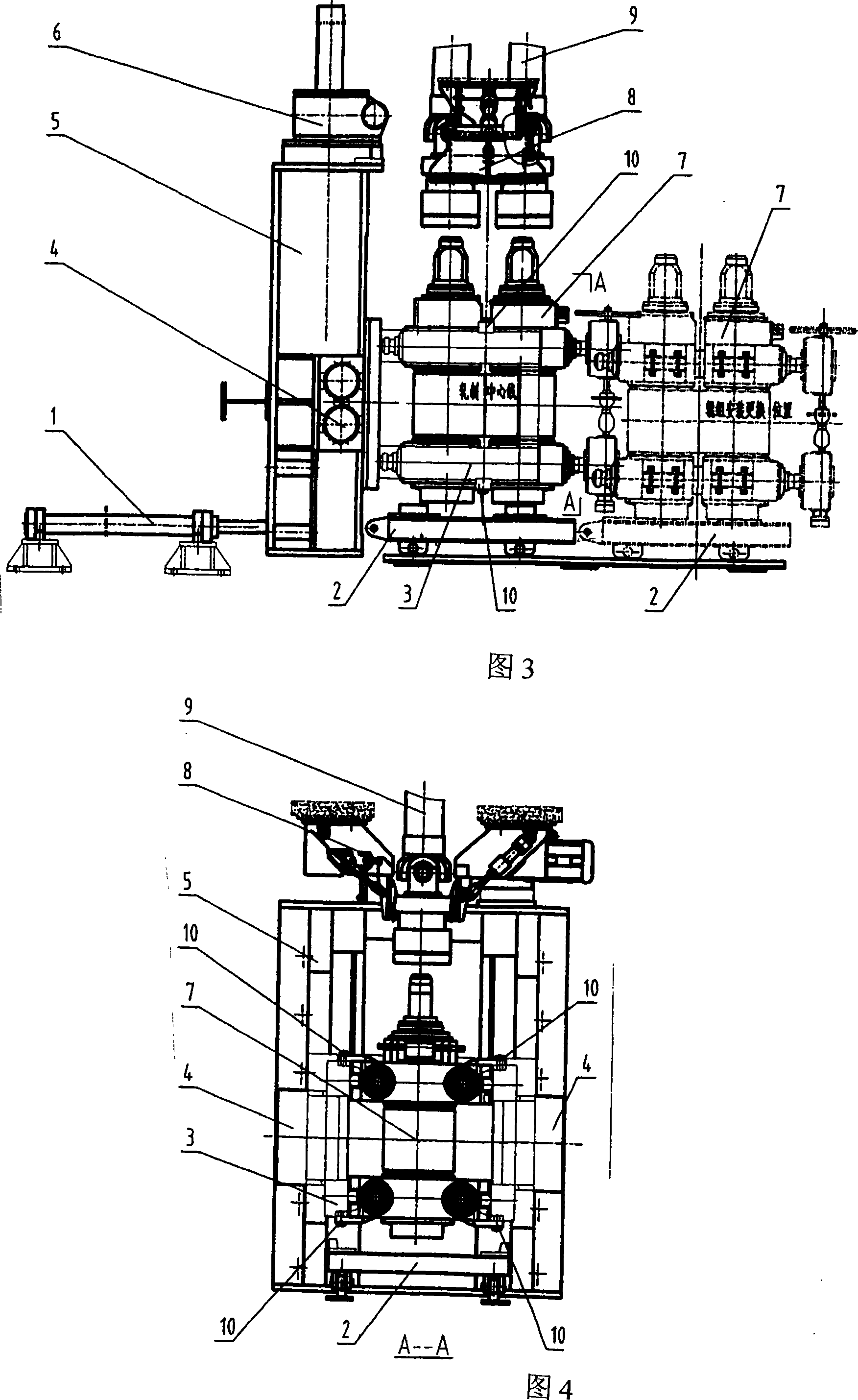
[0032] Roller group installation: put the roller group 7 on the roller changing trolley 2 (see Fig. 3, 4, 5, 6, 7), the roller changing hydraulic cylinder 1 works, and push the roller group 7 into the U-shaped bracket 3, consisting of One part in the groove rotation locking mechanism 10 --- the turning lug 13 is rotated into the groove of the U-shaped bracket 3, and the roller group 7 is fixed in the U-shaped bracket 3 with the connecting bolt 12; the worm gear lifter 6 works and the U-shaped After the bracket 3 and the roller group 7 are lifted to the working position, the rolling mill locking device 4 installed on the rolling mill base 5 is depressurized, and the piston rod 14 is pushed out by the elastic force of the disc spring 17, and the piston rod 14 locks the U-shaped bracket 3 On the rolling mill base 5 (see Figure 13).

[0033] Roll group replacement: Open the hydraulic control valve of the rolling mill locking device to retract the piston rod 14 in the rolling mill ...


PUM


Abstract

The invention relates to a frameless vertical short stress rolling mill. The feature is that the flute rotating locking structure is installed on the vertical shaft of the roller group through capping and sliding sleeve to ensure the rolling slot and flute rotating locking structure are on the same rolling line. The roller group keeps stability when adjusting the location of flute rotating locking structure. After installing roller group in U shaped frame, the rotating ear is driven to rotate to make the rotating ear block in the flute of the U shaped frame. Using bolt to fix the rotating ear in the flute of the U shaped frame, and fix the roller group in U shaped frame. The movement of roller locking device relies on piston rod. The advantages of the invention is that it has simple structure and machine work, light weight, convenience to replace roller group and decrease accident and improve produce efficiency.

Description

Technical field: [0001] The invention belongs to the field of metallurgical equipment, in particular to a vertical rolling mill. Background technique: [0002] Most of the existing vertical rolling mills are large and small frame type, the small frame is fixed on a large frame, the frame weight is heavy, the machining is difficult, the processing volume is large, and the cost is high. Vertical rolling mill. Not only that, because the frame rolling mill rolls are assembled in a closed frame (small frame), when changing the roll group (the working mechanism of the rolling mill), it must be extracted from the frame side window. In addition, the adjustment of the roll gap of the frame vertical rolling mill is to fix one roll and adjust the other roll. During the frequent adjustment of the roll gap opening of the rolling mill (in order to adapt to the change in the size of the rolled steel piece) and after changing the roll, The rolling line (i.e. the bisector of the centerline...

Claims


Application Information

Patent Timeline
Patent Type & Authority Applications(China)
IPC IPC(8): B21B31/02
Inventor 钟廷珍钟建瑜谭亮
Owner UNIV OF SCI & TECH BEIJING
Why Eureka
Try Eureka