Composite type connector lug in use for beam of car frame

A connecting joint and combined technology, which is applied to vehicle parts, substructure, transportation and packaging, etc., can solve problems such as prone to failure

Active Publication Date: 2007-12-26
CIMC VEHICLES (GROUP) CO LTD
View PDF0 Cites 8 Cited by
  • Summary
  • Abstract
  • Description
  • Claims
  • Application Information

AI Technical Summary

Problems solved by technology

[0008] The purpose of the present invention is to use bolts to directly connect the beams of each section for segmented frame structures that will bear torsion, bending, stretching, shearing, vibration or alternating stress due to different road conditions during actual use. Failure is prone to occur under complex stress condi

Method used


Image

  • Composite type connector lug in use for beam of car frame
  • Composite type connector lug in use for beam of car frame
  • Composite type connector lug in use for beam of car frame

Examples


Embodiment 1

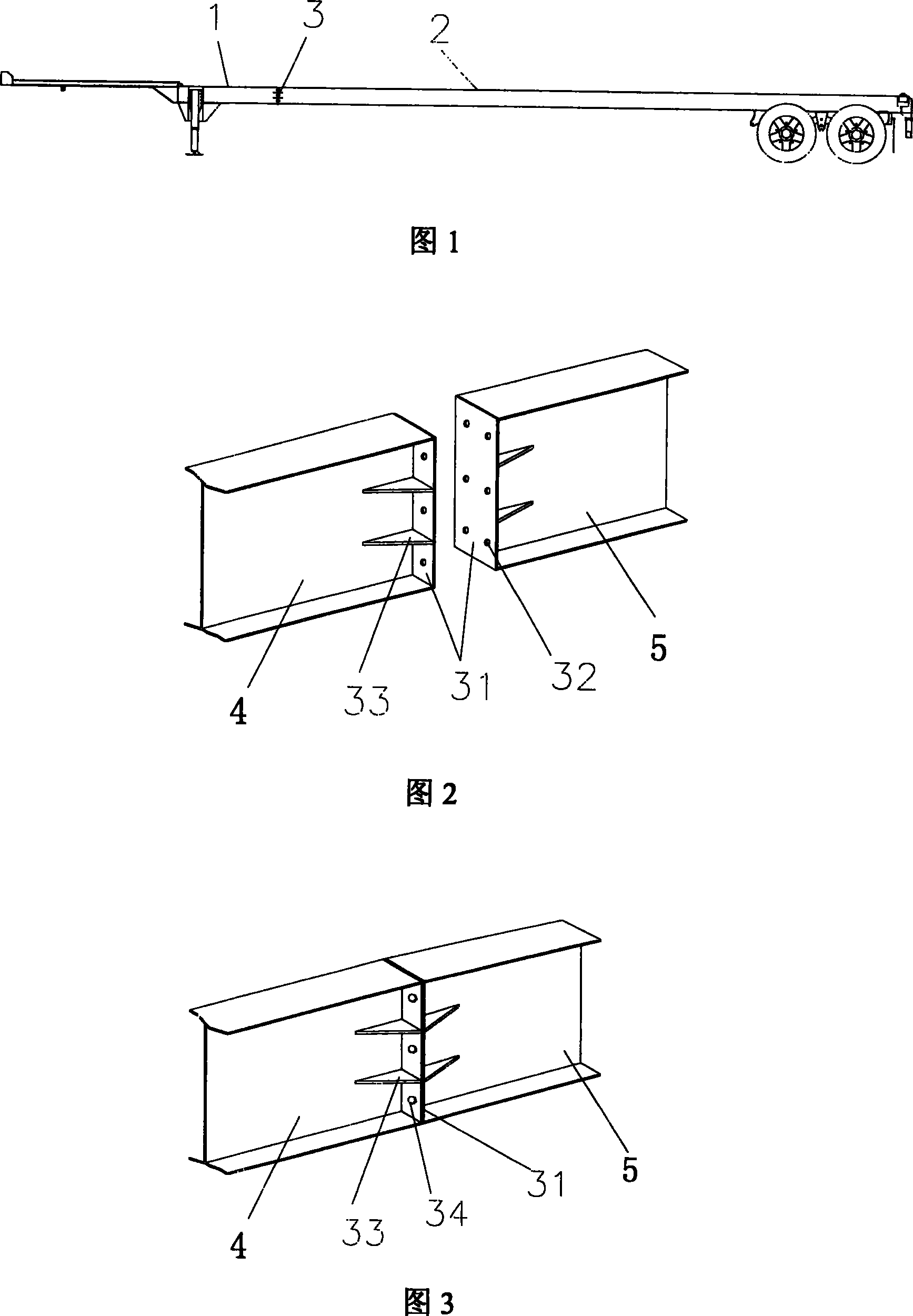
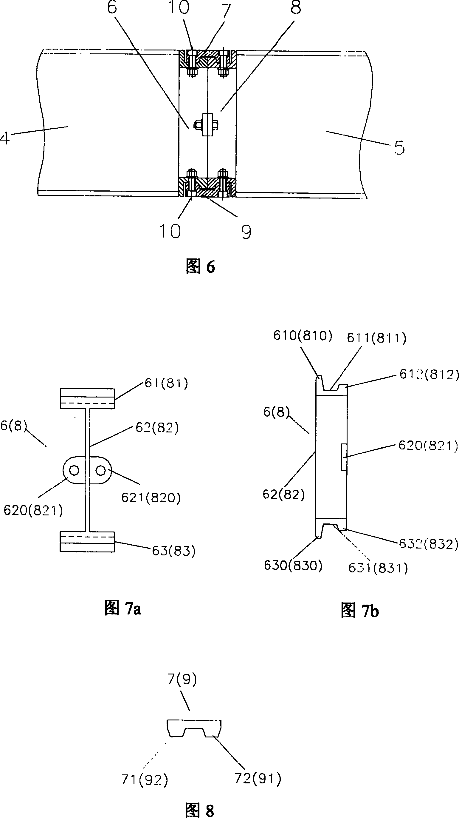
[0044] As shown in Fig. 7a, Fig. 7b, and Fig. 8, the connecting joint includes connecting seats 6, 8 and connecting pieces 7, 9, the cross section of the main beam of the frame is in the shape of "I", and the structure of the connecting seats 6, 8 is the same as that of Matching, the cross-section is also "I" shape; one side of the first connecting seat 6 is welded with the main beam 4 of the front section, the other side is connected with one side of the second connecting seat 8, and the other side of the second connecting seat 8 is connected with the rear Segment main beam 5 welding;

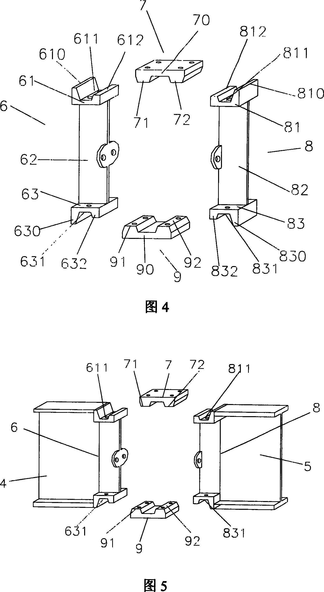
[0045] Wherein, the first connection base 6 includes a first base 61, a second base 63 and a connection portion 62 connecting the two bases; the two ends of the first base 61 and the connection portion 62 extend upward respectively, forming a first The protruding portion 610 and the second protruding portion 612, that is, the protruding portion extends in a direction parallel to the connecting...

Embodiment 2

[0052] As shown in Figure 10a, Figure 10b, Figure 11a, Figure 11b, and Figure 12, the connecting joint includes connecting seats 6, 8 and connecting pieces 7, 9. The structure of , 8 is matched with it, and the cross section is also in the shape of ""; one side of the first connecting seat 6 is welded with the main beam 4 of the front section, and the other side is connected with one side of the second connecting seat 8, and the second connecting seat 8 The other side of the main beam is welded with the main beam 5 of the rear section; the grooves 611, 631, 811, and 831 are all trapezoidal grooves, arranged in the vertical direction, arranged parallel to the web of the main beam "I" section steel, and perpendicular to its length direction; The protrusions 71 , 72 , 91 , 92 of the pieces 7 , 9 are trapezoidal structures matched with the grooves 611 , 631 , 811 , 831 .

Embodiment 3

[0054] As shown in Figure 13, the raised parts 71, 72, 91, 92 of the connectors 7, 9 are trapezoidal structures with a single slope, that is, the force-bearing surfaces 710, 720, 910, 920 of the raised parts are inclined planes, and the inclined planes and The grooves 611, 631, 811, 831 match the mating surfaces.

[0055] The stress-bearing surface of the protrusion may also be an arc surface.


PUM


Abstract

The invention relates to combined type connector lug used in carriage beam. It is divided into fixing part and connecting part. The connecting seat of the former is connected with the carriage main beam to be a whole. The connecting piece of the latter is connected with the connecting seat to be a whole. It has the advantages of using connecting piece to bear bending stress and tensile stress, big connect area to increase fastening function and connecting rigidity, high reliability, suiting for containerized transport semi-trailer with multiplex type main beam structure etc.

Description

technical field [0001] The invention belongs to the field of mechanical connection, and relates to a connection joint of a multi-section beam, in particular to a connection joint of a multi-section frame beam of a container semi-trailer. Background technique [0002] At present, the overall length of the inland container in the United States is 53 feet, and the semi-trailer transporting the 53-foot container is longer than the 53-foot container. After the semi-trailer is manufactured in China, it will be shipped to the United States by sea. There are two transportation options: one is to be transported by bulk carrier, and the other is to be transported by container ship. When transported by bulk carrier, it can be transported in the form of a whole vehicle, but it takes up a lot of space and the freight is high. In addition, there are few bulk carrier flights to meet delivery requirements. When transported by container ships, there are many flights and low freight rates, ...

Claims


Application Information

Patent Timeline
IPC IPC(8): B62D21/12
Inventor 谢良富沈礼庆
Owner CIMC VEHICLES (GROUP) CO LTD
Why Eureka
Try Eureka