
Vacuum coating equipment with transfer rollers for transferring flat substrates

A technology of vacuum coating and conveying rollers, applied in the directions of vacuum evaporation coating, coating, sputtering coating, etc., to avoid leakage, realize re-installation and easy re-installation

Inactive Publication Date: 2012-02-01
アプライドマテリアルズゲーエムベーハーウントツェーオーカーゲー
View PDF5 Cites 0 Cited by
  • Summary
  • Abstract
  • Description
  • Claims
  • Application Information

AI Technical Summary

Problems solved by technology

[0009] The present invention solves the problem of providing a transport device for flat substrates in a vacuum coating plant, wherein installation of the transport device in the vacuum coating plant can be achieved without great difficulty and removal of the transfer device from the vacuum coating device

Method used


Image

  • Vacuum coating equipment with transfer rollers for transferring flat substrates
  • Vacuum coating equipment with transfer rollers for transferring flat substrates
  • Vacuum coating equipment with transfer rollers for transferring flat substrates

Examples


Embodiment Construction

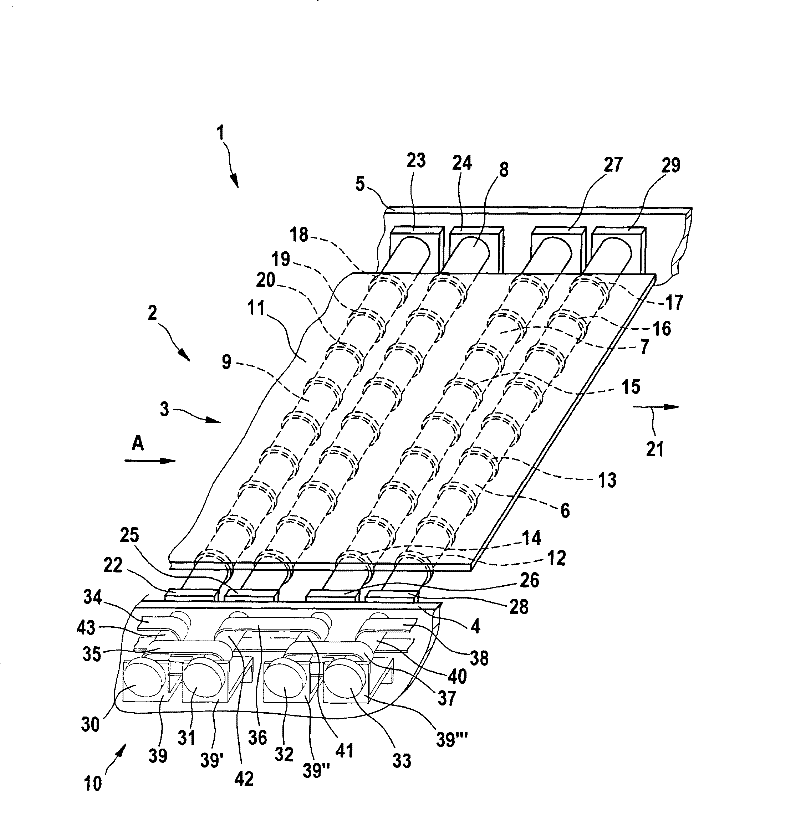
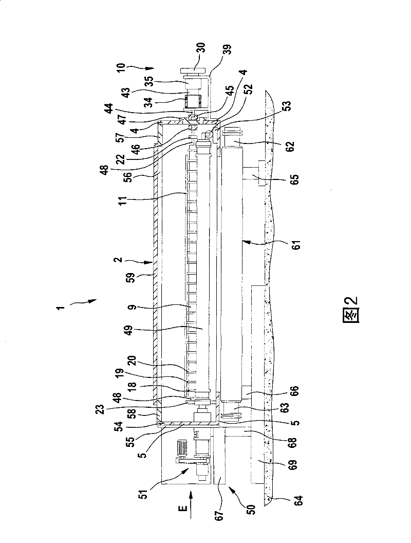
[0028] figure 1 A perspective view of a part of the vacuum coating chamber 2 in the vacuum coating device 1 is shown. Visible are parts of two opposing walls 4 , 5 delimiting the vacuum coating chamber 2 . The conveying device 3 is located in the vacuum coating chamber 2 and comprises several conveying rollers 6, 7, 8, 9 extending in parallel. These transport rollers 6 to 9 are driven via a drive system 10 located outside the vacuum coating chamber 2 . Under the action of the drive system 10, the transport rollers 6 to 9 undergo a rotational movement about their own longitudinal axes. The substrate 11 to be coated lies on transport rollers 6 to 9 . The substrate here is a flat substrate, such as architectural glass. In order that the substrate 11 does not rest directly on the transport rollers 6 to 9 , an elastic material, for example of the rubber type, can be applied to the outer sides of the transport rollers. This serves the purpose of preventing the substrate 11 from...


PUM


Abstract

The invention relates to a vacuum coating apparatus having a transport system for flat substrates which are transported through a vacuum chamber. This conveyor system consists of several cylinders arranged in parallel. One or several motors located inside or outside the vacuum chamber can be provided as drive means for these cylinders. The coupling between the motor or motors and the cylinder is in any case via a magnetic coupling device. Since no mechanical coupling is established between the drive and the cylinder, they can be easily separated from each other, which allows the cylinder and together with them the sputtering cathode to be arranged in a slide-in element that can be slid in and out of the vacuum chamber. . If not each cylinder is provided with its own drive, the cylinder to which the drive is coupled can be connected to other cylinders via V-belts or the like.

Description

technical field [0001] The present invention relates to vacuum coating equipment. Background technique [0002] The coating of the substrate takes place in a vacuum coating device whereby the particles are bombarded off the target, move in the direction towards the substrate and deposit thereon. In order to achieve a uniform coating of the substrate, the substrate and the target undergo a relative movement relative to each other, preferably the substrate moves past the target. [0003] Wherein the substrate is moved by a special transfer device. [0004] If large-area and substantially rigid substrates, such as architectural glass, are to be coated, a transport system comprising different continuous transport rollers is often used. These transport rollers are interconnected via toothed belts, chains and gears and are driven by a common drive (eg by an electric motor). [0005] A drive device for the shaft is known, which is located within the treatment chamber (US2005 / 020...

Claims


Application Information

Patent Timeline
Patent Type & Authority Patents(China)
IPC IPC(8): C23C14/34H01L21/677
CPCC23C14/564C23C14/3407C23C14/56H01F7/02
Inventor 尤尔根·亨利奇安德里亚斯·绍尔哈罗德·伍斯特埃德加·哈勃科恩
Owner アプライドマテリアルズゲーエムベーハーウントツェーオーカーゲー
Learn More